Cable well cable paving equipment

A cable well and cable technology, applied in the direction of cable laying equipment, etc., can solve the problems of shaking, winding, and weak support of the cable rack, and achieve the effect of preventing damage to the cable.

Active Publication Date: 2018-09-28
新沂市新南环保产业技术研究院有限公司
View PDF7 Cites 8 Cited by
  • Summary
  • Abstract
  • Description
  • Claims
  • Application Information

AI Technical Summary

Problems solved by technology

[0004] In order to solve the above problems, the present invention provides a cable laying equipment for cable wells, which can solve the problems that the existing cable racks cannot be locked for cable wells of different sizes, the support of the cable racks is not firm, and the cables cannot be fixed. When the transmission angle is adjusted on the cable well, the cable will rub against the side wall of the cable well, and there is a hidden danger that the cable will be entangled on the cable well escalator, and the cable will be entangled when it is transmitted in two directions. Shaking and other problems occur; it can realize the transmission of the cable outside the cable wellhead, and the angle-adjustable transmission of the cable in the cable well. It can be locked for different sizes of cable wells, and the cable frame is firmly supported. The transmission angle is adjusted on the well, the cable will not rub against the side wall of the cable well, there is no hidden danger of the cable being entangled on the escalator of the cable well, the cable will not be entangled when it is transmitted in two directions, and the transmission frame is not in place when the cable is transmitted in the cable well There will be shaking and other advantages

Method used


Image

  • Cable well cable paving equipment
  • Cable well cable paving equipment
  • Cable well cable paving equipment

Examples


Embodiment Construction

[0029] In order to make the technical means, creative features, goals and effects achieved by the present invention easy to understand, the present invention will be further described below in conjunction with specific illustrations. It should be noted that, in the case of no conflict, the embodiments in the present application and the features in the embodiments can be combined with each other.

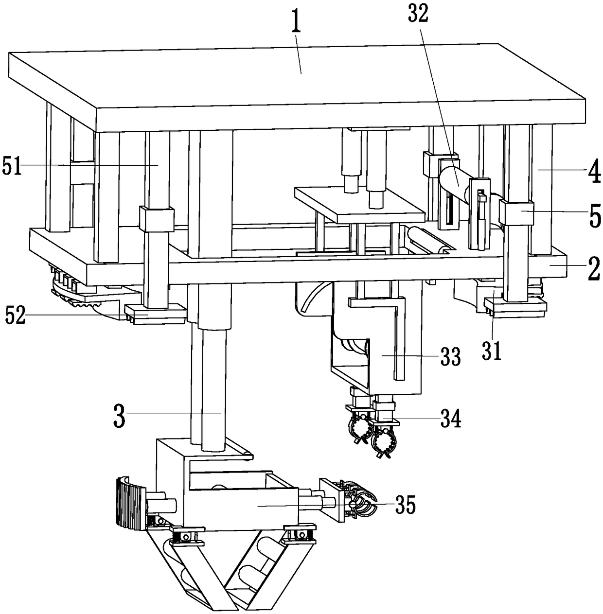
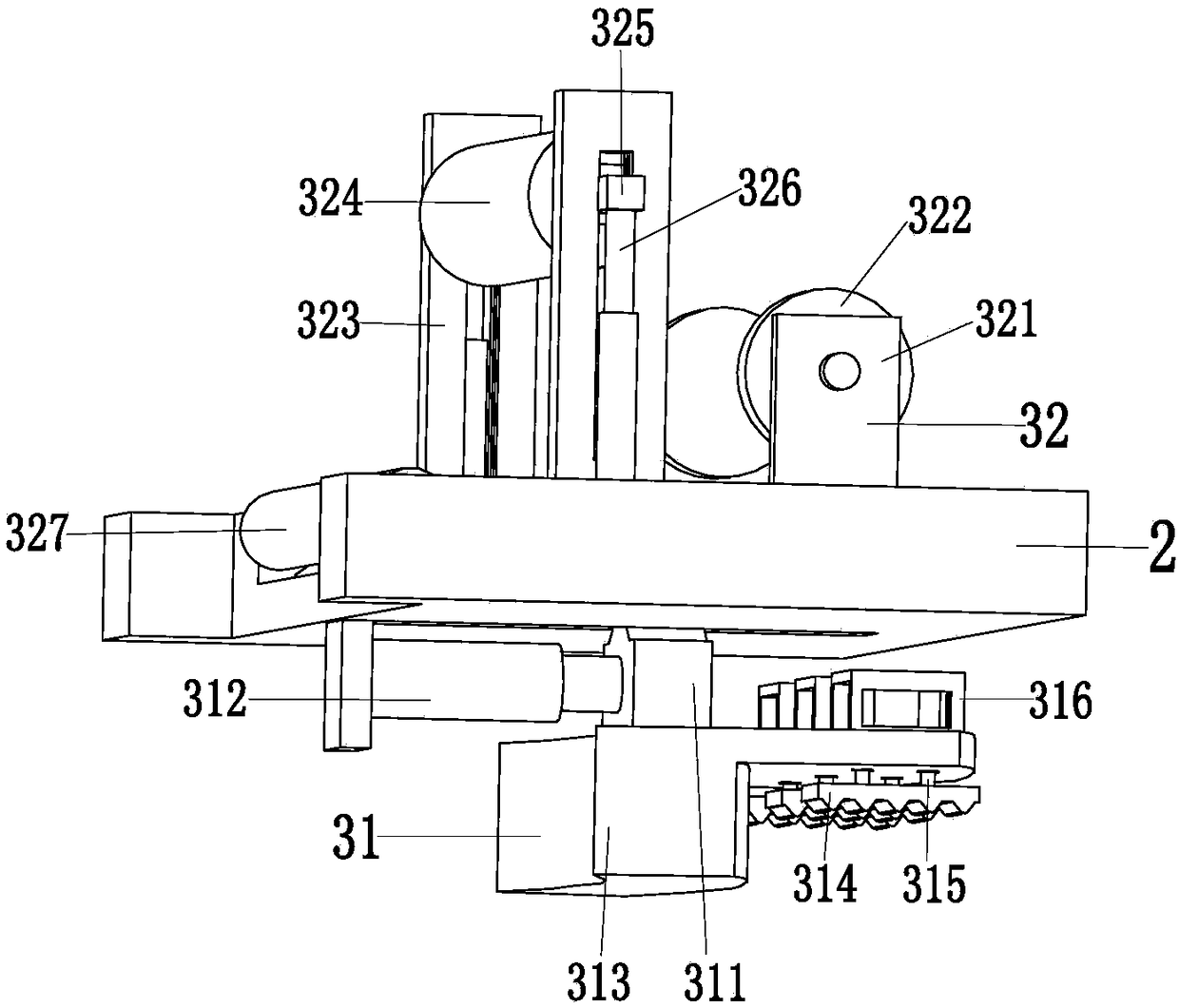
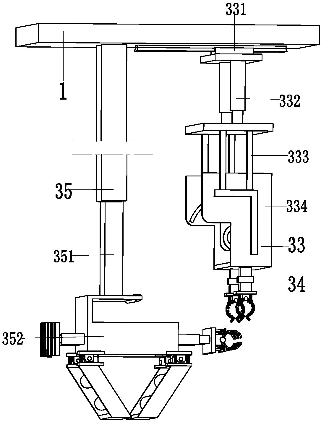
[0030] Such as Figure 1 to Figure 7 As shown, a cable laying equipment for a cable shaft includes a supporting top plate 1, a supporting bottom plate 2, a wire release device 3, a supporting connecting column 4 and a supporting mechanism 5, and a square groove is arranged on the middle part of the supporting bottom plate 2 to support The left and right ends of the bottom of the bottom plate 2 are provided with a chute, the support top plate 1 is installed on the top of the support bottom plate 2 through the support connecting column 4, and the support mechanism 5 is symmetrically in...


PUM


Abstract

The invention relates to cable well cable paving equipment. The cable well cable paving equipment comprises a support top plate, a support bottom plate, a paying-off device, a support connection column and support mechanisms, wherein a middle part of the support bottom plate is provided with a square slot; a left end and a right end of the bottom of the support bottom plate are provided with sliding chutes respectively; the support top plate is arranged on the top of the support bottom plate through the support connection column; the support mechanisms are symmetrically arranged at the bottomof an outer end of the support top plate; a right end of the paying-off device is arranged on the support bottom plate; and a left end of the paying-off device is connected with the bottom of the support top plate. Through adoption of the cable well cable paving equipment, the problems of incapability of adjusting the transmission angle of a cable on a cable well due to unstable support of an existing cable frame, potential safety hazard that the cable winds a ladder of the cable well due to friction between the cable and a side wall of the cable well, wobbling of a transmission frame during transmission of the cable in the cable well due to winding of the cable during transmission along two directions, and the like are solved.

Description

technical field [0001] The invention relates to the technical field of electric power construction, in particular to a cable laying equipment for a cable shaft. Background technique [0002] For the sake of the beauty of the city, bid farewell to the era of utility poles on the road. Now a large number of cables are conducted through underground cable wells. Now the city's infrastructure, subways, water pipes, etc. are basically underground, so the depth of the cable wells is also The deeper Larger and deeper cable wells will be equipped with escalators on their side walls to facilitate construction personnel to go up and down. The top of the cable well is equipped with a circular cable cover to reduce rainwater pouring into the cable well. [0003] The guide device in the cable well will be added when the deeper cable well is laid out, but this kind of guide device generally does not extend to the lower end of the cable well, so that the cable payout efficiency is low and t...

Claims


Application Information

Patent Timeline
Patent Type & Authority Applications(China)
IPC IPC(8): H02G1/06
CPCH02G1/06
Inventor 郑文豪
Owner 新沂市新南环保产业技术研究院有限公司
Why Eureka
Try Eureka