Medical disinfectant spraying equipment

A technology for disinfectant and medical use, which is applied in the direction of spraying devices, chemistry, etc., and can solve the problems of inconvenient adjustment of spraying direction and uneven spraying of disinfectant

Inactive Publication Date: 2018-11-06
GUILIN MEDICAL UNIVERSITY
View PDF6 Cites 11 Cited by
  • Summary
  • Abstract
  • Description
  • Claims
  • Application Information

AI Technical Summary

Benefits of technology

This patented technology describes an apparatus for dispensing liquids onto surfaces without requiring manual labor or complicated steps during operation by providing a mechanism called a mixing machine (mixer). It has three main parts: one consisting of a housing containing various components like motors, rollings, guards, and sprouts. These machines work together to create a thorough solution for cleaning materials such as foodstuffs. They have different ways to control how they operate, including controllable buttons/guns, pushbuttons, levers, and pulls. By connecting these mechanisms, users can easily switch between rotation modes based upon their preferences.

Problems solved by technology

This patented technical problem addressed by this patents relates to improving the efficiency at which healthcare workers clean their hands during patient care procedures while also ensuring they don't contaminate other areas around them due to incorrect dosage of germ-killing chemical being applied over nonhealthy surfaces such as door handles or tables.

Method used


Image

  • Medical disinfectant spraying equipment
  • Medical disinfectant spraying equipment
  • Medical disinfectant spraying equipment

Examples


Embodiment 1

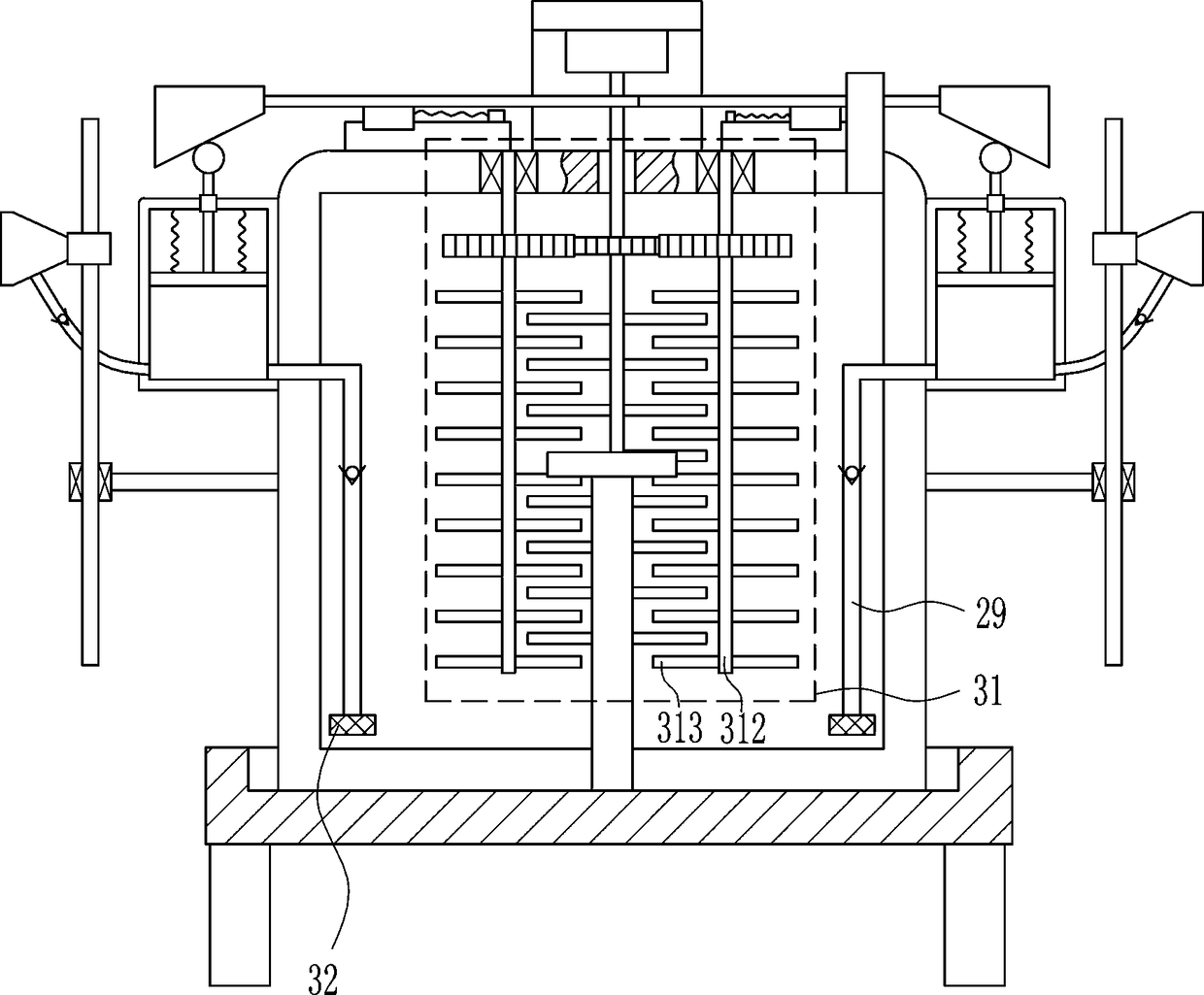
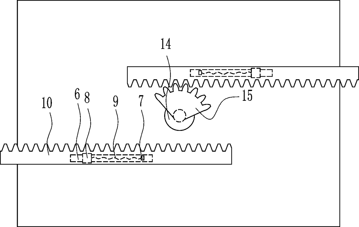
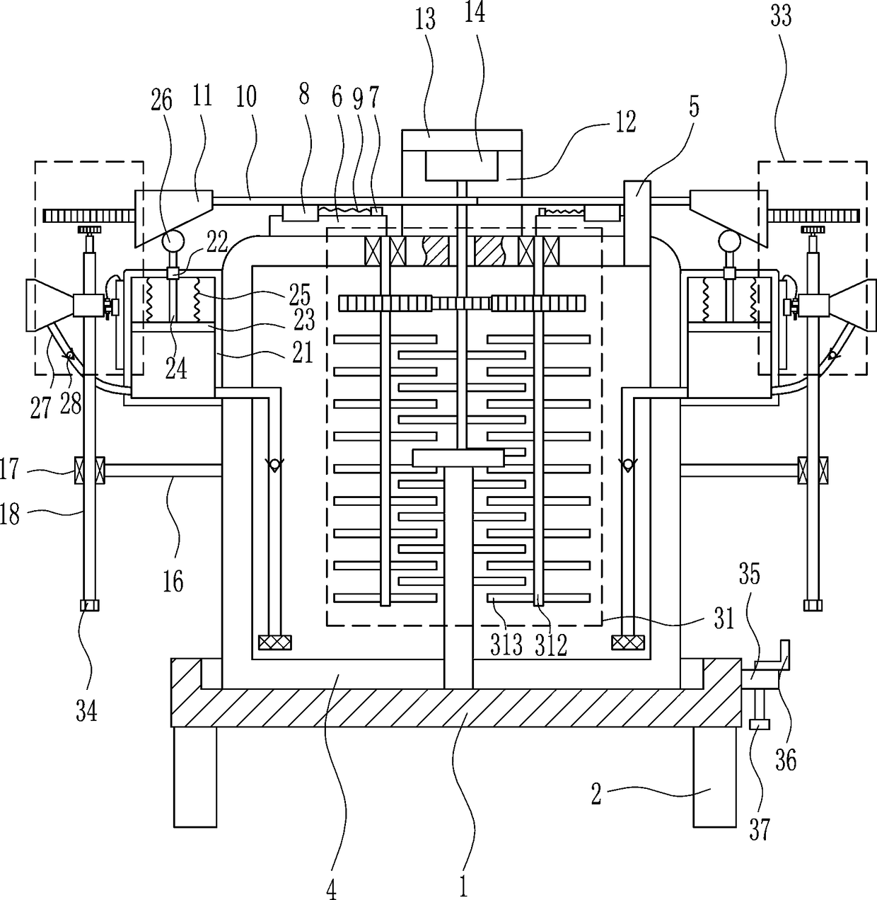
[0027] A medical disinfectant spraying equipment, such as Figure 1-7 As shown, it includes a placement frame 1, wheels 2, push handle 3, medicine box 4, feed pipe 5, first slide rail 6, fixed block 7, first slider 8, first spring 9, first rack 10 , Wedge block 11, connecting plate 12, mounting plate 13, motor 14, sector gear 15, connecting rod 16, first bearing seat 17, screw rod 18, first nut 19, nozzle 20, cylinder body 21, guide sleeve 22, Piston 23, guide rod 24, second spring 25, ball 26, flexible pipe 27, first one-way valve 28, L-shaped pipe 29 and second one-way valve 30, place frame 1 bottom left and right sides all are provided with wheels 2 , the middle part of the front side of the placement frame 1 is provided with a push handle 3, a medicine box 4 is placed in the placement frame 1, a feeding pipe 5 is provided on the right part of the upper wall of the medicine box 4, and a first slide is provided at the left front part of the top of the medicine box 4. Rail 6...

Embodiment 2

[0029] A medical disinfectant spraying equipment, such as Figure 1-7 As shown, it includes a placement frame 1, wheels 2, push handle 3, medicine box 4, feed pipe 5, first slide rail 6, fixed block 7, first slider 8, first spring 9, first rack 10 , Wedge block 11, connecting plate 12, mounting plate 13, motor 14, sector gear 15, connecting rod 16, first bearing seat 17, screw rod 18, first nut 19, nozzle 20, cylinder body 21, guide sleeve 22, Piston 23, guide rod 24, second spring 25, ball 26, flexible pipe 27, first one-way valve 28, L-shaped pipe 29 and second one-way valve 30, place frame 1 bottom left and right sides all are provided with wheels 2 , the middle part of the front side of the placement frame 1 is provided with a push handle 3, a medicine box 4 is placed in the placement frame 1, a feeding pipe 5 is provided on the right part of the upper wall of the medicine box 4, and a first slide is provided at the left front part of the top of the medicine box 4. Rail 6...

Embodiment 3

[0032] A medical disinfectant spraying equipment, such as Figure 1-7As shown, it includes a placement frame 1, wheels 2, push handle 3, medicine box 4, feed pipe 5, first slide rail 6, fixed block 7, first slider 8, first spring 9, first rack 10 , Wedge block 11, connecting plate 12, mounting plate 13, motor 14, sector gear 15, connecting rod 16, first bearing seat 17, screw rod 18, first nut 19, nozzle 20, cylinder body 21, guide sleeve 22, Piston 23, guide rod 24, second spring 25, ball 26, flexible pipe 27, first one-way valve 28, L-shaped pipe 29 and second one-way valve 30, place frame 1 bottom left and right sides all are provided with wheels 2 , the middle part of the front side of the placement frame 1 is provided with a push handle 3, a medicine box 4 is placed in the placement frame 1, a feeding pipe 5 is provided on the right part of the upper wall of the medicine box 4, and a first slide is provided at the left front part of the top of the medicine box 4. Rail 6,...


PUM


Abstract

The invention relates to spraying equipment, in particular to medical disinfectant spraying equipment. The medical disinfectant spraying equipment is uniform in spraying of disinfectant and convenientto adjust the spraying direction. The medical disinfectant spraying equipment comprises a placing frame, wheels, a pushing handle, a medicine box, a feed pipe, a first slide rail, a fixed block, a first slide block, a first spring, a first rack and the like; the wheels are arranged on the left and right sides of the bottom of the placing frame; the pushing handle is arranged at the middle part ofthe front side of the placing frame; the medicine box is placed in the placing frame; the feed pipe is arranged at the right part of the upper wall of the medicine box; and the first slide rail is arranged at the front part of the left side of the top of the medicine box. The medical disinfectant spraying equipment achieves the beneficial effects of uniform spraying of the disinfectant and convenience to adjust the spraying direction; through cooperation of a screw rod and a first nut, the convenient adjustment of the nozzle direction is realized; and through arrangement of a rotating device,the self direction of a nozzle can be automatically adjusted, so that the disinfectant is sprayed more uniformly.

Description


Claims


Application Information

Patent Timeline
Owner GUILIN MEDICAL UNIVERSITY
Why Eureka
Try Eureka