Spinning punch transplanter

A transplanting machine and hole technology, which is applied to transplanting machinery, planting methods, excavation/covering trenches, etc., can solve the problems of low degree of automation, high labor intensity, inconvenient use, etc. High work efficiency and guaranteed accuracy

Inactive Publication Date: 2018-11-13
SOUTH CHINA AGRI UNIV
View PDF7 Cites 2 Cited by
  • Summary
  • Abstract
  • Description
  • Claims
  • Application Information

AI Technical Summary

Problems solved by technology

[0004] The purpose of the present invention is to solve the problem that the transmission mechanism of the existing transplanting machine usually uses a flexible shaft to transmit power, and the engine and the transplanting machine are not integrally installed together, but by installing the engine on a back frame and carrying it manually For the problems of low degree of automation, high labor intensity, inconvenient use, and low operating efficiency, a spinning hole punching transplanter with light structure, simple use, high working efficiency, safety and reliability is provided.

Method used


Image

  • Spinning punch transplanter
  • Spinning punch transplanter
  • Spinning punch transplanter

Examples


Embodiment 1

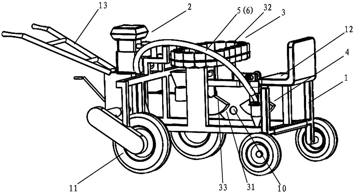
[0024] refer to Figure 1 to Figure 3 , the present embodiment relates to a transplanter, including a vehicle frame 1, a driving device 2, a seedling throwing device 3 and a hole-making device 4, and the driving device 2, the seedling throwing device 3 and the hole-making device 4 are installed on the vehicle frame 1, The bottom of the vehicle frame 1 is provided with a wheel 11, and the power output end of the driving device 2 is connected with the power input end of the wheel 11 and the punching device 4; People's seat 12, and the rear end of vehicle frame 1 is provided with the handle 13 that is used for manually pushing vehicle frame 1; The seedling throwing outlet 31 of described seedling throwing device 3 is corresponding to the bottom of punching device 4 and seedling 10 is thrown into In the cave hole punched out by the hole punching device 4.

[0025] When working, the seedling shooter sits on the seat 12, and the driver controls the traveling direction of the vehicl...

Embodiment 2

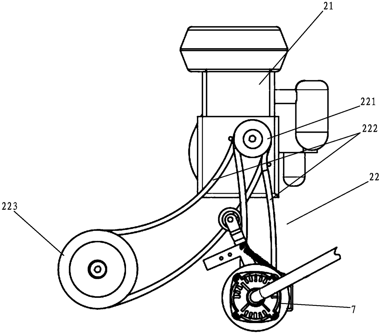
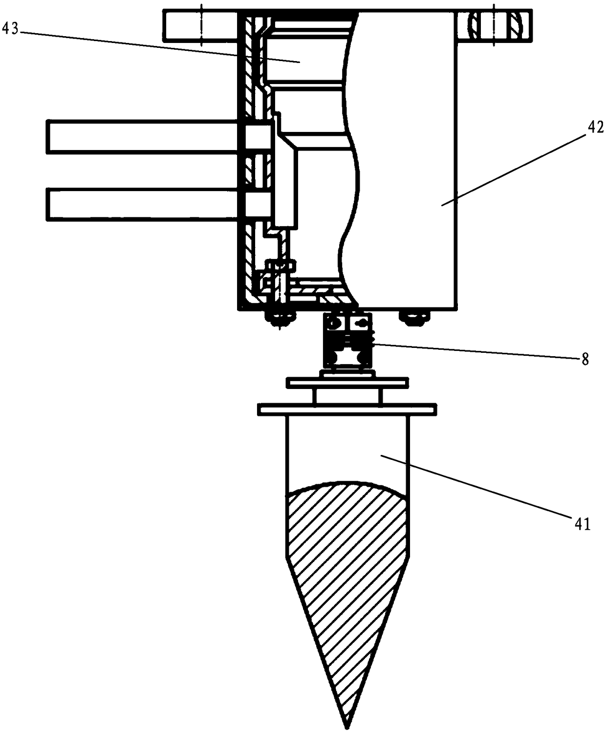
[0032]This embodiment is based on Embodiment 1, and as an improvement to the punching device 4, the punching device 4 includes a mounting base 42, a hydraulic motor 43 and a punching head 41, and the mounting base 42 is installed on the vehicle frame 1, the hydraulic motor 43 is installed on the mounting base 42, and the hydraulic motor 43 is connected to the power output end of the driving device 2 through the pipeline 6 and the hydraulic pump 7, and the acupuncture head 41 is fixed to the output shaft of the hydraulic motor 43 connect. When working, the engine 21 drives the hydraulic pump 7 to work through the transmission mechanism 22, so that the hydraulic pump 7 outputs hydraulic oil to the hydraulic motor 43 and drives the hydraulic motor 43 to drive the acupuncture head 41 to rotate.

[0033] In order to facilitate the connection between the acupuncture head 41 and the hydraulic motor 43 , the acupuncture head 41 is fixedly connected to the output end of the hydraulic m...


PUM


Abstract

The invention discloses a spinning punch transplanter which includes a frame, a driving device, a seedling dropping device and a punch device, wherein the driving device, the seedling dropping deviceand the punch device are mounted on the frame; wheels are arranged at the bottom of the wheels; the power output of the driving device is connected with the wheels and the power input end of a punch head; the front end of the frame is used for bearing a seat of a seedling dropping people, and handles used for pushing the frame by hands of the people are arranged at the rear end of the frame; a seedling dropping outlet of the seedling dropping device corresponds to the bottom of the punch device, so that seedlings are dropped to caves caved by the punch device. According to the invention, the driving device and the punch device are mounted into a whole by the frame, and the driving device drives the punch device to move to movably cave the furrow slice of a ridging body, so that the spinning punch transplanter has the advantages of simple structure, convenience in use, high working efficiency, safety and reliability.

Description

technical field [0001] The invention belongs to the research field of agricultural transplanting equipment, in particular to a spinning hole punching and transplanting machine. Background technique [0002] The traditional method of transplanting and punching holes is manually punching holes, or using a knapsack puncher, and then planting the seedlings in the holes to complete the transplanting after punching holes. This artificial hole-punching method has high labor intensity and low efficiency, and is only suitable for small-area planting. And the transmission system of general transplanting machine adopts chain transmission, when assembling machinery, because transmission mechanism structure is complicated, not only assembling process is troublesome but also the space that chain transmission mechanism takes is big, and it is inconvenient to use. [0003] The transmission mechanism of the existing punching type transplanting machine usually uses a flexible shaft to transm...

Claims


Application Information

Patent Timeline
Patent Type & Authority Applications(China)
IPC IPC(8): A01C5/04A01C11/02
CPCA01C5/04A01C11/02
Inventor 贾瑞昌何振峰方丹玲刘文岳
Owner SOUTH CHINA AGRI UNIV
Why Eureka
Try Eureka