PDT cluster system auxiliary control channel design method

An auxiliary control channel and control channel technology, applied in wireless communication, network traffic/resource management, electrical components, etc., can solve the problems of poor flexibility, limiting the access volume of a single PDT cluster base station terminal, etc., to achieve good compatibility and low cost Cost business stability becomes worse and the effect of reducing air interface overhead

Active Publication Date: 2018-11-16
EASTERN COMM
View PDF6 Cites 3 Cited by
  • Summary
  • Abstract
  • Description
  • Claims
  • Application Information

AI Technical Summary

Problems solved by technology

[0004] Although the functions of the existing PDT standard system are relatively complete, there is still room for improvement in performance. There is a contradiction between limited air interface resources and increasing user demand, and common problems such as uplink collision and downlink congestion are still bottlenecks. These inherent Insufficiency limits the terminal access volume of a single PDT cluster base station
In areas with concentrated and busy business, the project usually adopts the solution of adding base stations to solve the problem. It relies on guiding terminals to be distributed to different base stations to alleviate the access pressure of a single base station. This solution is more effective for fixed-point busy areas, but for some large There are still limitations in safeguarding activities with strong mobility in a large number of terminal areas, and the temporary erection of base stations requires consideration of time and economic costs as well as the difficulty of subsequent maintenance, and the flexibility is poor

Method used


Image

  • PDT cluster system auxiliary control channel design method
  • PDT cluster system auxiliary control channel design method
  • PDT cluster system auxiliary control channel design method

Examples


Embodiment Construction

[0039] The invention is an auxiliary control channel design scheme aimed at alleviating the pressure of the dedicated control channel. It should be noted that all the solutions involved in this article are designed based on the concept of being compatible with standards.

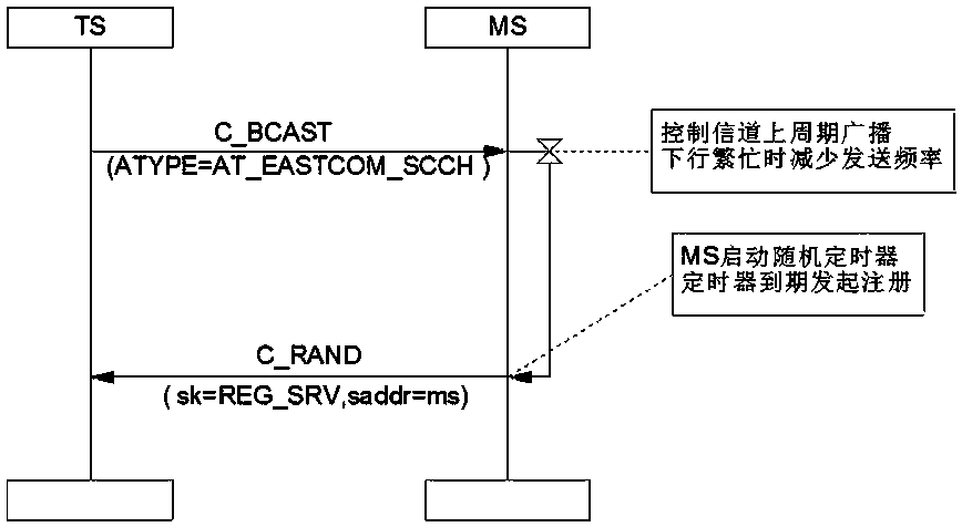
[0040] On a PDT cluster base station, in addition to the dedicated control channel, one or more auxiliary control channels are set, so that some terminals can register on the auxiliary control channel for business. The dedicated control channel and the auxiliary control channel are collectively called the control channel. The auxiliary control channel Except that the channel can be set and canceled, other applications are exactly the same as the dedicated control channel, which is the basic concept of the PDT auxiliary control channel in this solution.

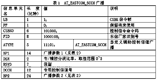
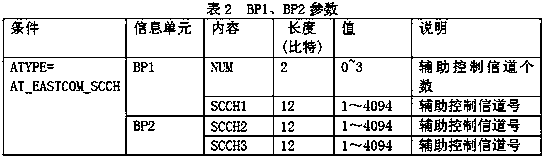
[0041] On the system, the auxiliary control channel can be manually set through the network management or MML commands. The base station sends the informati...


PUM


Abstract

The invention relates to a PDT cluster system auxiliary control channel design method. The PDT cluster system auxiliary control channel design method is characterized in that: one or more auxiliary control channels are set while setting a dedicated control channel on a PDT cluster base station, so that part terminals can register to the auxiliary control channels for business, wherein the dedicated control channel and the auxiliary control channels are collectively called control channels; the auxiliary control channels can be set and cancelled, and other applications of the auxiliary controlchannels are completely consistent with the dedicated control channel. The invention uses a single base station to achieve the purpose of terminal shunting without adding the erection of system equipment; compared with the shunting mode with multiple base stations, the PDT cluster system auxiliary control channel design method has the advantages such as low cost, low maintenance difficulty, higherflexibility and so on. Meanwhile, the scheme can flexibly control the terminal shunting through setting a shunting ratio, which has strong adaptability to the changeable field requirements. The terminal can seamlessly transform the control channel in the idle state without affecting normal business, therefore, the product has higher fluency.

Description

technical field [0001] The invention relates to a method for designing an auxiliary control channel of a PDT cluster system. Background technique [0002] In the PDT standardized trunking system, the base station needs at least one control channel to support terminal access, call establishment, short message service, supplementary service, etc. Almost all PDT trunking services require the participation of control channels, and each service needs to consume a certain amount of air interface resources. When the number of network-connected terminals reaches a certain level, uplink signaling collisions and downlink signaling congestion often occur, thereby affecting the service success rate and reducing product experience and customer satisfaction. [0003] The PDT standard is a trunking communication standard with independent intellectual property rights in China. It is based on the development of digital intercom and draws on international mature standard technologies such as...

Claims


Application Information

Patent Timeline
IPC IPC(8): H04W28/08H04W36/00H04W36/06H04W36/22H04W64/00H04W84/08
CPCH04W36/0011H04W36/06H04W36/22H04W64/003H04W84/08H04W28/082
Inventor 张小琴涂书忠叶萌朱达宇
Owner EASTERN COMM
Why Eureka
Try Eureka