Hard alloy pipe fitting

A technology of cemented carbide and pipe fittings, which is used in metal processing machinery parts, metal processing equipment, parts of boring machines/drilling machines, etc. Quality preparation speed and other issues to achieve the effect of preventing deviation, improving drilling efficiency and stability

Inactive Publication Date: 2018-12-21
广州峥航机械设备有限公司
View PDF0 Cites 0 Cited by
  • Summary
  • Abstract
  • Description
  • Claims
  • Application Information

AI Technical Summary

Problems solved by technology

[0002] In the production and processing of cemented carbide pipe fittings, the drilling work of traditional cemented carbide pipe fittings mainly relies on workers holding the punching machine to perform manual drilling. Although this is greatly conducive to convenient and quick drilling operations, there are problems Yes, in the process of manual drilling, because only manual experience is used to align the drill bit with the cemented carbide pipe, people's hands are prone to shake when drilling, so it is easy to make the hole crooked, which greatly It affects the quality and speed of the preparation of cemented carbide pipe fittings, and the traditional drilling equipment is inconvenient to adjust the rotation direction and disassembly of the drill bit. Therefore, the drilling limitations are strong and inconvenient to use, which affects the production and processing efficiency of cemented carbide pipe fittings. needs improvement

Method used


Image

  • Hard alloy pipe fitting
  • Hard alloy pipe fitting
  • Hard alloy pipe fitting

Examples


Embodiment Construction

[0014] Combine below Figure 1-4 The present invention will be described in detail.

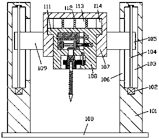
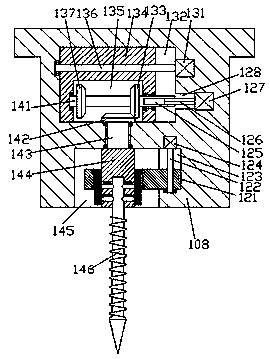
[0015] refer to Figure 1-4 , a cemented carbide pipe fitting according to an embodiment of the present invention, comprising a base 100, a support frame 101 is fixed symmetrically on the top end surface of the base 100, and a main base body is arranged between the support frames 101 on the left and right sides 107, the first sliding cavity 113 is provided in the bottom end surface of the main seat body 107, and the mounting seat 108 is installed in the sliding fit in the first sliding cavity 113, and the top surface of the mounting seat 108 is connected with the first sliding cavity 113 A buffer spring 112 is installed between the top walls, and a first concave cavity 145 is provided in the bottom end surface of the mounting seat 108, and a first transmission is provided in the mounting seat 108 on the upper side of the first concave cavity 145. cavity 132, the part between the first conca...


PUM


Abstract

The invention discloses a hard alloy pipe fitting. The hard alloy pipe fitting comprises a base. Supporting frames are symmetrically and fixedly arranged on the top end surface of the base left and right. A main seat body is arranged between the supporting frames on the left and right sides. A first sliding cavity is arranged in the bottom end surface of the main seat body. A mounting seat is installed in the first sliding cavity in a sliding fit manner. A buffer spring is installed between the top end surface of the mounting seat and the top wall of the first sliding cavity in an abutting fitmanner. A first concave cavity is formed in the bottom end surface of the mounting seat. A first transmission cavity is arranged in the portion, on the upper side of the first concave cavity, of themounting seat. A first rotating shaft is rotatably arranged between the first concave cavity and the first transmission cavity in a matched mode. A first bevel gear is fixedly arranged at the tail endof the top of the first rotating shaft. A mounting block is fixedly arranged at the tail end of the bottom of the first rotating shaft. An insertion cavity is formed in the bottom end surface of themounting block.

Description

technical field [0001] The invention relates to the technical field of pipe fitting processing, in particular to a cemented carbide pipe fitting. Background technique [0002] In the production and processing of cemented carbide pipe fittings, the drilling work of traditional cemented carbide pipe fittings mainly relies on workers holding the punching machine to perform manual drilling. Although this is greatly conducive to convenient and quick drilling operations, there are problems Yes, in the process of manual drilling, because only manual experience is used to align the drill bit with the cemented carbide pipe, people's hands are prone to shake when drilling, so it is easy to make the hole crooked, which greatly It affects the quality and speed of the preparation of cemented carbide pipe fittings, and the traditional drilling equipment is inconvenient to adjust the rotation direction and disassembly of the drill bit. Therefore, the drilling limitations are strong and inc...

Claims


Application Information

Patent Timeline
Patent Type & Authority Applications(China)
IPC IPC(8): B23B41/00B23B47/20B23Q5/10B23Q5/28B23Q5/34
CPCB23B41/00B23Q5/10B23Q5/28B23Q5/34
Inventor 韦红生
Owner 广州峥航机械设备有限公司
Why Eureka
Try Eureka