Injection molding machine

A technology of injection molding machine and injection head, which is applied in the field of injection molding machines, can solve problems such as low production efficiency and easy blockage of nozzles, and achieve the effect of improving production efficiency

Inactive Publication Date: 2019-01-18
鹤山市金利源五金塑料制品有限公司
View PDF0 Cites 8 Cited by
  • Summary
  • Abstract
  • Description
  • Claims
  • Application Information

AI Technical Summary

Problems solved by technology

[0003] The existing injection molding machine has low production efficiency, and because the plastic is easy to cool and solidify at the nozzle position, the nozzle is easy to block

Method used


Image

  • Injection molding machine
  • Injection molding machine

Examples


Embodiment Construction

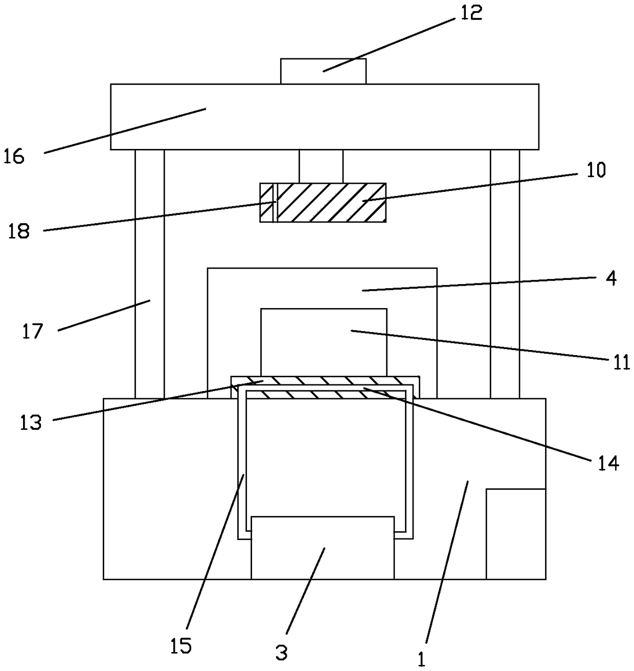
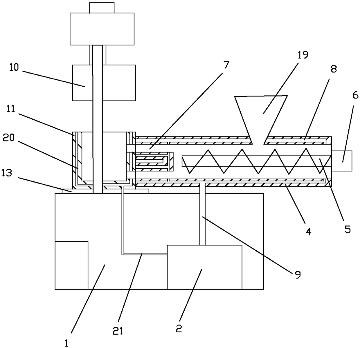
[0017] Such as figure 1 and figure 2 As shown, an injection molding machine includes a frame 1, an oil reservoir 2 for storing and heating heat transfer oil and a water reservoir 3 for storing cooling water are installed in the frame 1, and an injection molding mechanism is installed above the frame 1 And the clamping mechanism, the injection molding mechanism includes a heater 4 and a screw rod 5 for driving plastic discharge, the screw rod 5 is installed in the heater 4 and is connected with a servo motor 6 for driving the screw rod 5 to rotate along its own axis, and the heater 4 is provided with Two injection molding heads 7 for pouring plastic, the heater 4 and the inner wall of the injection molding head 7 are provided with a first cavity 8 for accommodating heat transfer oil, the first cavity 8 communicates with the oil reservoir 2 through an oil delivery pipeline 9, and is combined. The mold mechanism comprises an upper mold 10 and a lower mold 11 which cooperate wit...


PUM


Abstract

The invention discloses an injection molding machine. The injection molding machine comprises a machine seat, wherein an oil receiver and a water receiver are installed in the machine seat, an injection molding mechanism and a mold closing mechanism are installed above the machine seat, the injection molding mechanism comprises a heater and a threaded rod, the threaded rod is installed in the heater and connected with a servo motor, the heater is provided with two injection molding heads, the inner walls of the heater and the injection molding heads are provided with first cavities, and the first cavities are communicated with the oil receiver; the mold closing mechanism comprises an upper mold body and a lower mold body, the upper mold body is connected with a driving air cylinder, a moldcarrying disc used for installing the lower mold body is installed on the machine seat, a cooling pipeline is arranged in the mold carrying disc, and the cooling pipeline is communicated with the water receiver. The injection molding machine achieves injection through the two injection heads, has the high injection efficiency, and can avoid the situation that production cannot be operated becauseone injection head is abnormal. The injection molding heads are communicated with heat conducting oil, so that the situation that plastics is conveyed to the injection molding heads and cooled and solidified, and accordingly the injection molding heads are blocked is avoided. The mold carrying disc can be cooled through cooling water, thus the lower mold body is cooled, cooling of the plastic product is accelerated, and the production efficiency is improved.

Description

technical field [0001] The invention relates to the technical field of plastic production equipment, in particular to an injection molding machine. Background technique [0002] Injection molding is to use the thermophysical properties of plastics to put materials from the hopper into the barrel. The outside of the barrel is heated by a heating ring to melt the materials. A screw connected to the injection motor is installed in the barrel. The material is driven by the screw along the The screw groove is conveyed forward and compacted, and the material is gradually plasticized, melted and homogenized under the double action of external heating and screw shearing. The melted material is pushed to the head of the screw, and at the same time, the screw retreats under the reaction of the material, so that the head of the screw forms a storage space and completes the plasticizing process. Then, the screw is driven by the piston thrust of the hydraulic system to With high speed a...

Claims


Application Information

Patent Timeline
Patent Type & Authority Applications(China)
IPC IPC(8): B29C45/03B29C45/34B29C45/74B29C45/73B29C45/18
CPCB29C45/03B29C45/18B29C45/34B29C45/7312B29C45/74
Inventor 曹界伟
Owner 鹤山市金利源五金塑料制品有限公司
Why Eureka
Try Eureka