A decoction device for biomedicine

A biomedicine and decoction technology, which is applied in the field of traditional Chinese medicine processing, can solve the problems of affecting the decoction of medicines, inconvenient fast drinking, long cooling time, etc., and achieve the effects of short cooling time, easy drinking, and increased extraction volume

Active Publication Date: 2021-04-20
吴慧东
View PDF11 Cites 0 Cited by
  • Summary
  • Abstract
  • Description
  • Claims
  • Application Information

AI Technical Summary

Problems solved by technology

[0003] In the existing equipment for decocting traditional Chinese medicine, only most of the medicinal liquid is discharged from the equipment after the decoction is completed, while part of the medicinal liquid in the medicinal residues cannot be discharged from the equipment; After the medicine is decocted, its temperature is usually high, and it needs to be cooled for a long time, so on the one hand, it is not convenient to drink quickly, and on the other hand, the cooling time is long, which affects the subsequent decoction of the medicine

Method used


Image

  • A decoction device for biomedicine
  • A decoction device for biomedicine
  • A decoction device for biomedicine

Examples


Embodiment 1

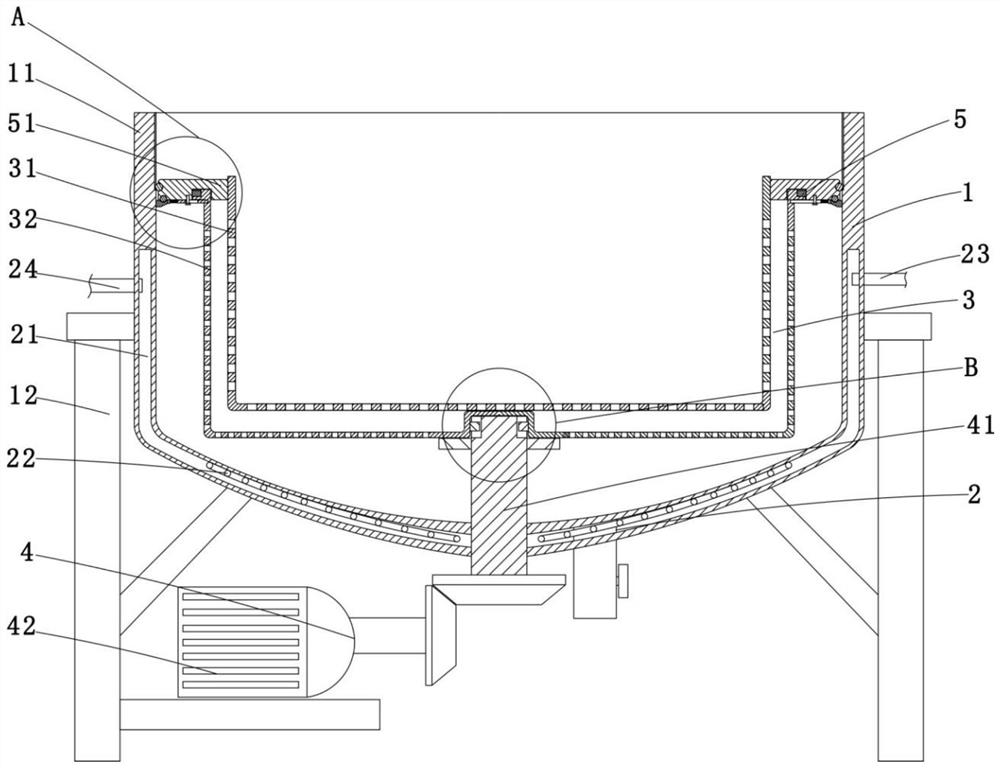
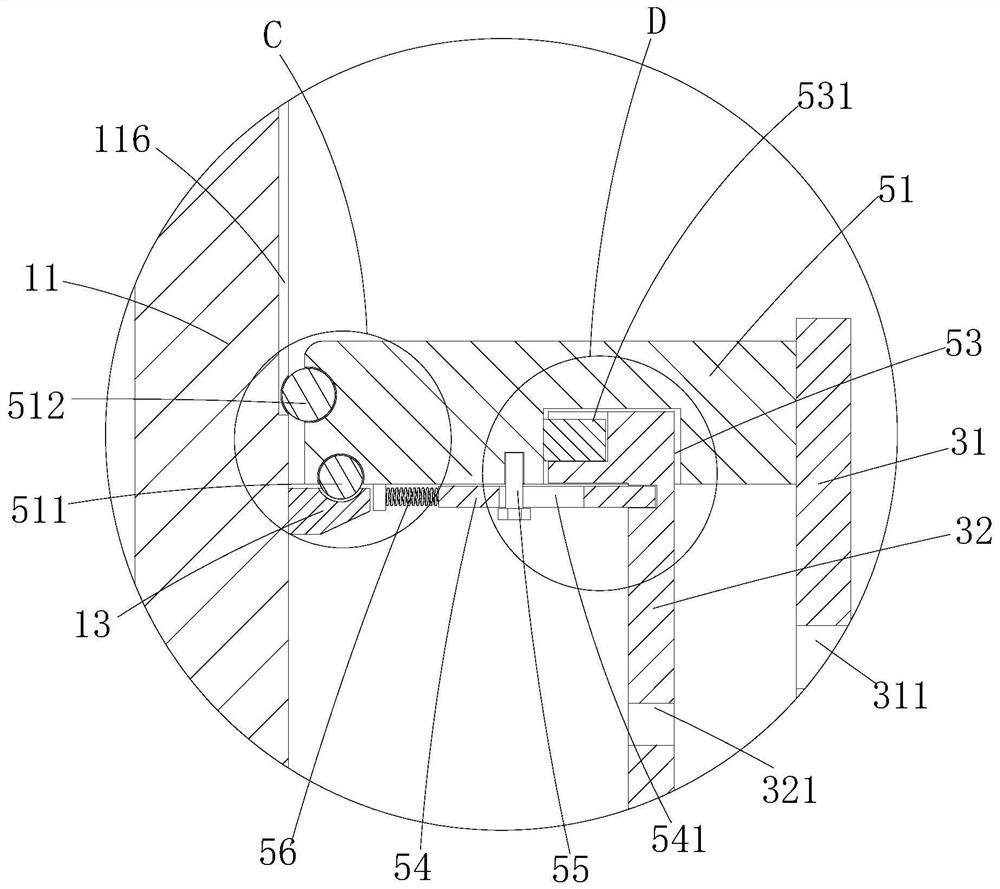
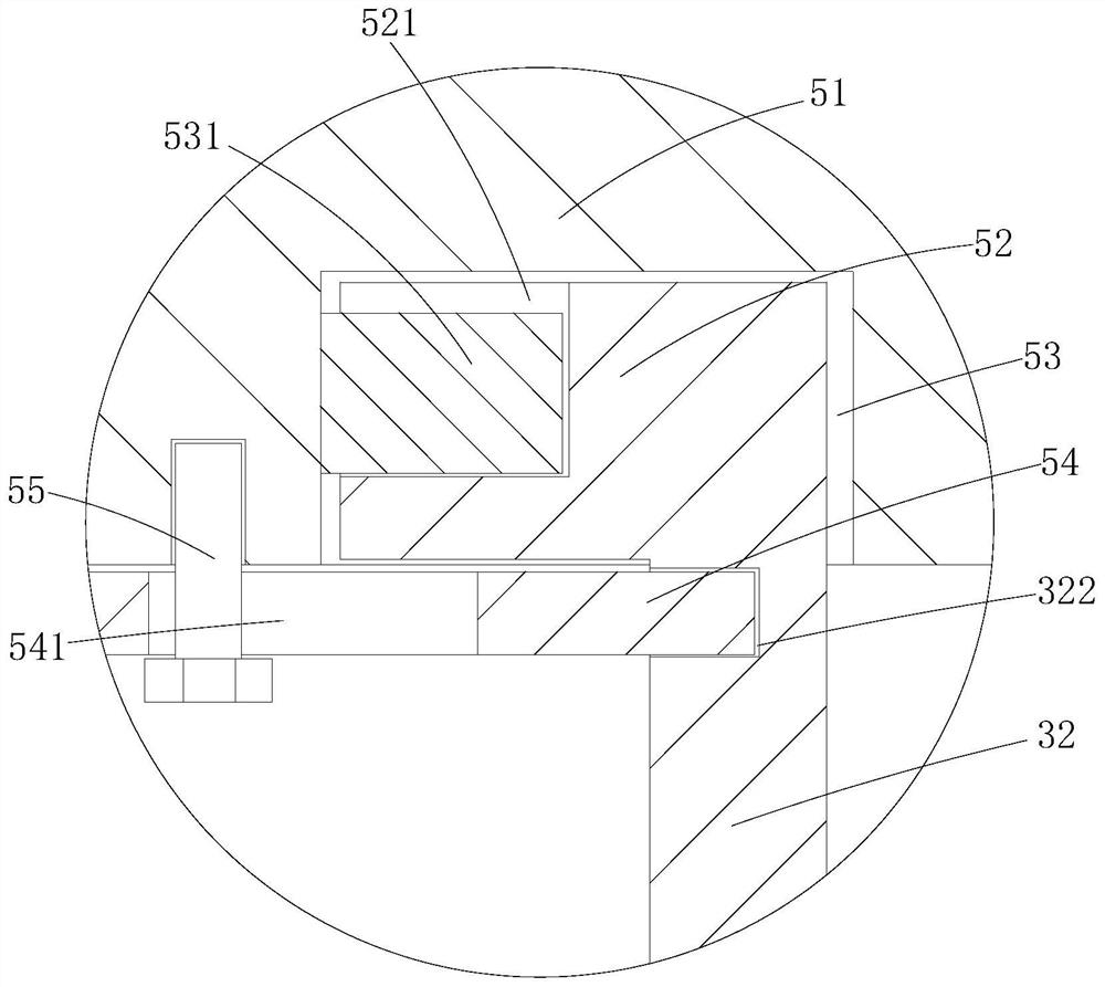
[0034] Such as Figure 1-7 As shown, a biomedical decoction device includes a reaction tank 1, a heating part 2, a liquid removal part 3 and a driving part 4, wherein the reaction tank 1 includes a tank body 11 and a bracket 12, and the tank body 11 It is a metal tank, the bracket 12 is a metal frame, and the bracket 12 is connected to the tank body 11; the heating component 2 is arranged on the tank body 11, and the heating component 2 includes a The heating chamber 21 on the upper surface and the heating element 22 arranged in the heating chamber 21, the heating element 22 is a resistance wire, the heating element 22 is arranged in the heating chamber 21, when the heating element 22 is heated , the heating element 22 can raise the temperature of the material in the tank body 11 to a specified temperature; a steam inlet pipe 23 and a steam outlet pipe 24 are communicated on the heating chamber 21, so that the steam inlet pipe 23 can flow to the heating chamber Steam is sent ...

Embodiment 2

[0041] Such as Figure 8-9 As shown, the difference between this embodiment and Embodiment 1 is that a stirring component is added to stir the material in the first filter element, specifically: the stirring component 6 includes an air inlet pipe 61, a heating element 62 and an air supply element 63 , wherein the air intake pipe 61 is an L-shaped metal pipe, the air supply part 63 is a fan, the air supply part 63 is connected with the air intake pipe 61, and the heating part 62 is a heating wire , the heating element 62 is located in the air intake pipe 61; a filter screen 64 is arranged in the air intake pipe 61, and the filter screen 64 is a metal mesh, and the filter screen 64 and the air intake pipe 61 detachable connections.

[0042] Further, the inlet pipe 61 is provided with a socket 611, the filter 64 can be inserted through the socket 611, and a sealing layer 641 is bonded on the left and right side walls of the filter 64, the sealing The layer 641 is a rubber layer...

Embodiment 3

[0044] Such as Figure 10-12 As shown, the difference between this embodiment and Embodiment 1 is that this embodiment has a discharge component, specifically: the discharge component 7 includes a discharge pipe 71, a valve 72, a cooling chamber 73, an inlet pipe 74, an outlet Liquid pipeline 75 and liquid supply pipeline 76, described discharge pipeline 71 is a metal pipeline, and described discharge pipeline 71 is connected with the bottom of described tank body 11; Rib 711, the heat dissipation rib 711 is a metal sheet; the valve 72 is a ball valve, and the valve 72 is arranged on the discharge pipeline 71; the cooling chamber 73 is located on the side wall of the discharge pipeline 71 The upper layer of cavity, the liquid inlet pipe 74 and the liquid outlet pipe 75 are all connected with the cooling chamber 73, so that the liquid inlet pipe 74 passes into the cooling chamber 73 and cold water is passed into the outlet pipe 71. The liquid medicine is cooled.

[0045] Furt...


PUM


Abstract

The invention discloses a decoction device for biomedicine, which comprises a reaction tank for decocting materials, including a tank body and a bracket connected with the tank body; a heating part is arranged on the tank body and is used for heating The material in the tank; the discharge part is connected with the tank and is used to discharge the liquid medicine, including a discharge pipe, a valve arranged on the discharge pipe, and a valve provided on the discharge pipe. The cooling chamber, the liquid inlet pipe and the liquid outlet pipe, the liquid inlet pipe and the liquid outlet pipe are all in communication with the cooling chamber. The present invention can facilitate the discharge of the material from the discharge pipe by setting the discharge part, and the cooling liquid can be passed into the cooling chamber during the process, so that the liquid medicine can be quickly cooled when the liquid medicine is discharged, thereby reducing the temperature The short time allows for quick drinking.

Description

technical field [0001] The invention belongs to the technical field of traditional Chinese medicine processing, in particular to a decoction device for biomedicine. Background technique [0002] Traditional Chinese medicine decoction refers to the medicine that puts the medicinal materials in water for decoction or soaking in boiling water, then removes the slag and then obtains the liquid. the therapeutic effect. [0003] In the existing equipment for decocting traditional Chinese medicine, only most of the medicinal liquid is discharged from the equipment after the decoction is completed, while part of the medicinal liquid in the medicinal residues cannot be discharged from the equipment; After the medicine is decocted, its temperature is usually high, and it needs to be cooled for a long time, so on the one hand, it is not convenient to drink quickly, and on the other hand, the cooling time is long, which affects the subsequent decoction of the medicine. Contents of th...

Claims


Application Information

Patent Timeline
Patent Type & Authority Patents(China)
IPC IPC(8): A61J3/00
CPCA61J3/00A61J2200/40
Inventor 吴慧东
Owner 吴慧东
Why Eureka
Try Eureka