Hybrid control synchronous valve

A technology of hybrid control and synchronizing valve, applied in control valve, valve detail, multi-port valve and other directions, can solve the problem of low synchronization accuracy of synchronization valve, and achieve the effect of reducing outflow, improving work efficiency and improving synchronization accuracy.

Active Publication Date: 2019-04-23
GUANGDONG IND TECHN COLLEGE
View PDF12 Cites 6 Cited by
  • Summary
  • Abstract
  • Description
  • Claims
  • Application Information

AI Technical Summary

Problems solved by technology

[0006] The purpose of the present invention is to overcome the shortcomings and deficiencies of the prior art, and provide a hybrid control synchronous valve to solve the problem of low synchronization accuracy of the synchronous valve, improve the control accuracy at the same time, greatly save costs, and improve work efficiency

Method used


Image

  • Hybrid control synchronous valve

Examples


Embodiment

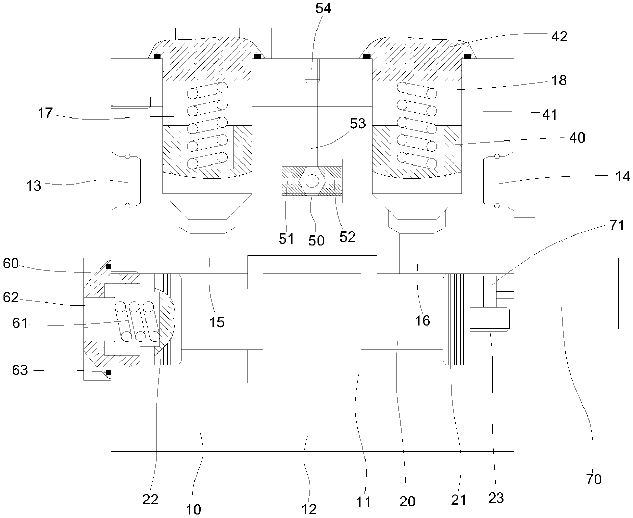
[0021] Please refer to figure 1 , a mixing control synchronous valve, including a valve body 10, the lower part of the valve body 10 is provided with an oil inlet chamber 11, the oil inlet chamber 11 is provided with a main valve core 20, and the valve body 10 is provided with an oil inlet port under the oil inlet chamber 11 12. On both sides of the upper part of the valve body 10, the left oil outlet 13 and the right oil outlet 14 are respectively connected. The oil chamber 11 is connected, and the valve body 10 is provided with a left oil chamber 17 above the left passage 15, and a right oil chamber 18 above the right passage 16;

[0022] The left oil chamber 17 and the right oil chamber 18 are provided with an oil outlet valve core 40; the left and right ends of the main valve core 20 are respectively provided with a left piston 22 and a right piston 21; There is a control part 23 at the right end of the main valve core 20, and the drive unit 70 makes the main valve core 2...


PUM


Abstract

A hybrid control synchronous valve comprises a valve body of which the lower part is provided with an oil inlet cavity, and the oil inlet cavity is internally provided with a main valve core; an oil inlet is formed in the position, below the oil inlet cavity, of the valve body, and the both side faces of the upper part of the valve body are provided with a left oil outlet and a right oil outlet separately; the left oil outlet communicates with the oil inlet cavity through a left channel, and the right oil outlet communicates with the oil inlet cavity through a right channel; a left oil cavityis arranged at the position, above the left channel, of the valve body, and a right oil cavity is arranged at the position, above the right channel, of the valve body; the left oil cavity and the right oil cavity are provided with oil outlet valve cores; the right and left ends of the main valve core are provided with a right piston and a left piston, and the right side of the valve body is provided with a driving unit; the right end of the right piston is provided with a control part; the left end of the oil inlet cavity is provided with a through hole which is provided with an oil inlet sealing bolt, and a spring is arranged between the oil inlet sealing bolt and the left piston; and the upper ends of the left oil cavity and the right oil cavity are provided with through holes which areprovided with oil outlet sealing bolts, and springs are arranged between the oil outlet sealing bolts and the oil outlet valve cores. According to the hybrid control synchronous valve, the control accuracy is improved, and the cost is saved greatly; and the wording efficiency is improved.

Description

technical field [0001] The invention relates to the technical field of synchronous valves, in particular to a mixing control synchronous valve. Background technique [0002] The synchronous valve is used to ensure that two or more actuators (hydraulic cylinders or hydraulic motors) can still obtain the same or a certain proportion of flow when they are subjected to different loads, so that the same displacement or the same displacement between the actuators A hydraulic component that moves at high speed, the synchronous valve is used to synchronize the lifting mechanism. In the use of the synchronous lifting mechanism, a hydraulic valve is basically used to control an actuator. During the lifting process, due to the difference in working resistance, the lifting of the pillars is not synchronized, which causes the speed to be out of sync and affects the movement accuracy. The typical structure of the traditional synchronous valve is the hook type and the reversing piston typ...

Claims


Application Information

Patent Timeline
Patent Type & Authority Applications(China)
IPC IPC(8): F15B13/02F16K11/07F16K15/04F16K15/18F16K17/28F16K17/30F16K31/04F16K31/54
CPCF15B13/02F16K11/07F16K15/04F16K17/285F16K17/30F16K31/047F16K31/54F16K15/1823
Inventor 廖辉蔡云妹李湘伟
Owner GUANGDONG IND TECHN COLLEGE
Why Eureka
Try Eureka