An optical fingerprint module and electronic equipment

A fingerprint module and optical technology, applied in the optical field, can solve the problems of the mechanical reliability of the module, affect the performance of the module, and the glue is easy to overflow, and achieve the effect of reducing the size, improving the performance and reducing the cost.

Pending Publication Date: 2019-05-07
昆山丘钛生物识别科技有限公司
View PDF0 Cites 1 Cited by
  • Summary
  • Abstract
  • Description
  • Claims
  • Application Information

AI Technical Summary

Problems solved by technology

[0005] 1. It is necessary to avoid the micro-lens area for gluing, so the filter needs to be designed in a larger size and the cost is higher;
[0006] 2. The glue is easy to overflow to the micro-lens area, which affects the performance of the module;
[0007] 3. The glue is close to the metal wire, and it is easy to overflow the glue to the metal wire to produce a chemical reaction, which will affect the performance of the module;
[0008] 4. The bottom of the filter is hollow, and the mechanical reliability of the module is at risk

Method used


Image

  • An optical fingerprint module and electronic equipment
  • An optical fingerprint module and electronic equipment
  • An optical fingerprint module and electronic equipment

Examples


Embodiment 1

[0050] This embodiment provides an optical fingerprint module, which can be installed under the screen of an electronic device (such as a smart phone, or a tablet computer, etc.), for example, installed under an OLED screen, and the user can place the finger on the on the screen, so that the fingerprint recognition operation can be performed on the screen.

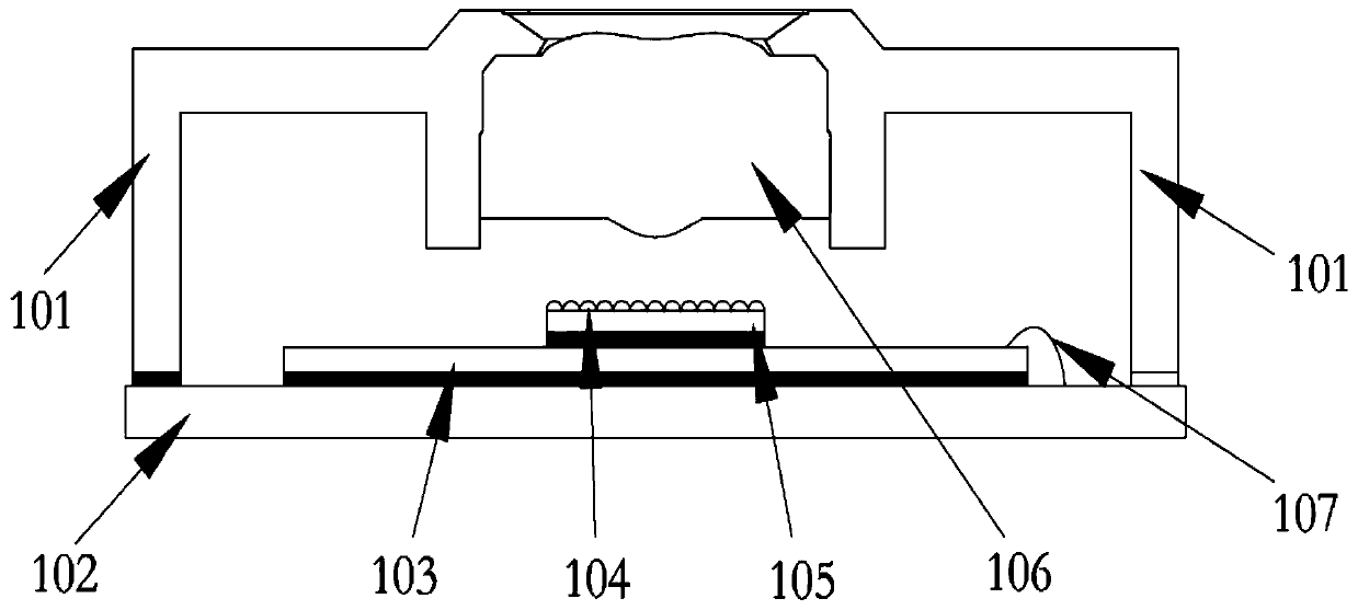
[0051] like figure 1 As shown, the optical fingerprint module includes:

[0052] Circuit substrate 102;

[0053] The bracket 101 is arranged on the circuit substrate 102;

[0054] The lens 106 is arranged on the bracket 101;

[0055] The fingerprint chip 103 is arranged on the circuit substrate 102 and below the lens 106, and the fingerprint chip 103 is electrically connected to the circuit substrate 102;

[0056] The optical filter 105 is arranged on the fingerprint chip 103;

[0057] The microlens 104 (also known as: micro-convex lens array; English name: micro-lens) is arranged on the filter 105 .

[0058] As an o...

Embodiment 2

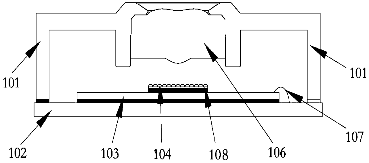
[0079] Based on the same inventive concept, this embodiment provides an optical fingerprint module with another structure, such as figure 2 As shown, the difference from Embodiment 1 is that in this embodiment, the filter 105 is omitted, but a layer of filter film 108 is covered on the lower surface of the microlens 104 .

[0080] Specifically, if figure 2 As shown, the optical fingerprint module includes:

[0081] Circuit substrate 102;

[0082] The bracket 101 is arranged on the circuit substrate 102;

[0083] The lens 106 is arranged on the bracket 101;

[0084] The fingerprint chip 103 is arranged on the circuit substrate 102 and below the lens 106, and the fingerprint chip 103 is electrically connected to the circuit substrate 102;

[0085] The microlens 104 is arranged on the fingerprint chip 103 , and the lower surface of the microlens 104 is covered with a filter film 108 .

[0086] As an optional embodiment, the fingerprint chip 103 is pasted on the circuit sub...

Embodiment 3

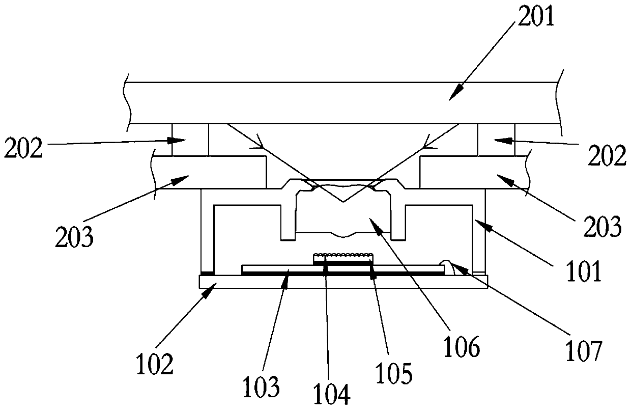
[0102] Based on the same inventive idea, such as image 3 As shown, this embodiment provides an electronic device, including:

[0103] OLED screen 201;

[0104] The optical fingerprint module is arranged under the OLED screen 201 .

[0105] In a specific implementation process, the electronic device may be: a smart phone, or a tablet computer, or a digital camera, or a game console, or the like. This embodiment does not specifically limit what kind of device the electronic device is.

[0106] In a specific implementation process, the optical fingerprint module is specifically as shown in Embodiment 1 or Embodiment 2. exist image 3 Only the situation in the first embodiment is shown, and the optical fingerprint module in the second embodiment is also applicable to the electronic device in this embodiment.

[0107] In a specific implementation process, the optical fingerprint module can be fixed under the middle frame 203 of the electronic device (for example, the middle f...


PUM


Abstract

The invention discloses an optical fingerprint module. The optical fingerprint module comprises: a circuit substrate; The bracket which is arranged on the circuit substrate; The lens which is arrangedon the bracket; The fingerprint chip which is arranged on the circuit substrate and is electrically connected with the circuit substrate; The light filtering element which is positioned on the fingerprint chip; And the micro lens which is positioned on the light filtering element. The technical problems that in an optical fingerprint module in the prior art, an optical filter needs to be designedto be large in size, and cost is high are effectively solved, and therefore the technical effect that the size of the optical filter is reduced or the optical filter is cancelled, and cost is reducedis achieved.

Description

technical field [0001] The invention relates to the field of optical technology, in particular to an optical fingerprint module and electronic equipment. Background technique [0002] With the rapid development of the mobile Internet era, the integrated functions of mobile phones have become more complete. Now, the size of the screen has also developed to a critical point. In order to pursue better visual effects, another form of appearance innovation - "full screen" Came into being. The arrival of a full screen will inevitably lead to changes in fingerprint recognition technology. [0003] At present, in order to realize the full-screen solution, each mobile phone terminal has an under-screen fingerprint solution: the most mainstream one is the "optical fingerprint + OLED screen" solution. In this solution, the micro-lens (micro lens) is pasted on the photosensitive area of ​​the fingerprint chip, the filter is pasted on the fingerprint chip with structural glue, and the ...

Claims


Application Information

Patent Timeline
Patent Type & Authority Applications(China)
IPC IPC(8): G06K9/00
Inventor 邹兵陈亮
Owner 昆山丘钛生物识别科技有限公司
Why Eureka
Try Eureka