A New Ultra-High Pressure Piston Pump

A technology of ultra-high pressure and plunger pumps, which is applied in the direction of pumps, pump components, multi-cylinder pumps, etc., and can solve the problems that cannot meet the working requirements of ultra-high pressure plunger pumps, processing errors and assembly errors cannot be overcome, and fluid-solid thermal multi-field coupling Effect enhancement and other issues, to achieve the effect of compact structure, improved service life and small volume

Active Publication Date: 2020-03-31
YANSHAN UNIV
View PDF12 Cites 0 Cited by
  • Summary
  • Abstract
  • Description
  • Claims
  • Application Information

AI Technical Summary

Problems solved by technology

[0004] The hydraulic pump is the core power component to ensure the operation of the hydraulic system. The ultra-high pressure will cause the internal load of the plunger pump to increase, the multi-field coupling effect of fluid-solid heat to increase, and the key friction pairs of the plunger pump to be stuck. Errors and assembly errors cannot be overcome, causing the pump to generate axial unbalanced force and affecting the performance of the pump
The traditional plunger pump design can no longer meet the working requirements of ultra-high pressure plunger pumps. It is urgent to improve the existing axial plunger pumps so that they can meet the requirements of different occasions and sizes. It has the characteristics of saving energy, reducing pollution, simple preparation and suitable for large-scale production

Method used


Image

  • A New Ultra-High Pressure Piston Pump
  • A New Ultra-High Pressure Piston Pump
  • A New Ultra-High Pressure Piston Pump

Examples


Embodiment Construction

[0030] The present invention will be described in detail below in conjunction with the accompanying drawings, and the embodiments described here are only some of the embodiments of the present invention, not all of them. Based on the embodiments of the present invention, all other embodiments obtained by persons of ordinary skill in the art without creative efforts fall within the protection scope of the present invention.

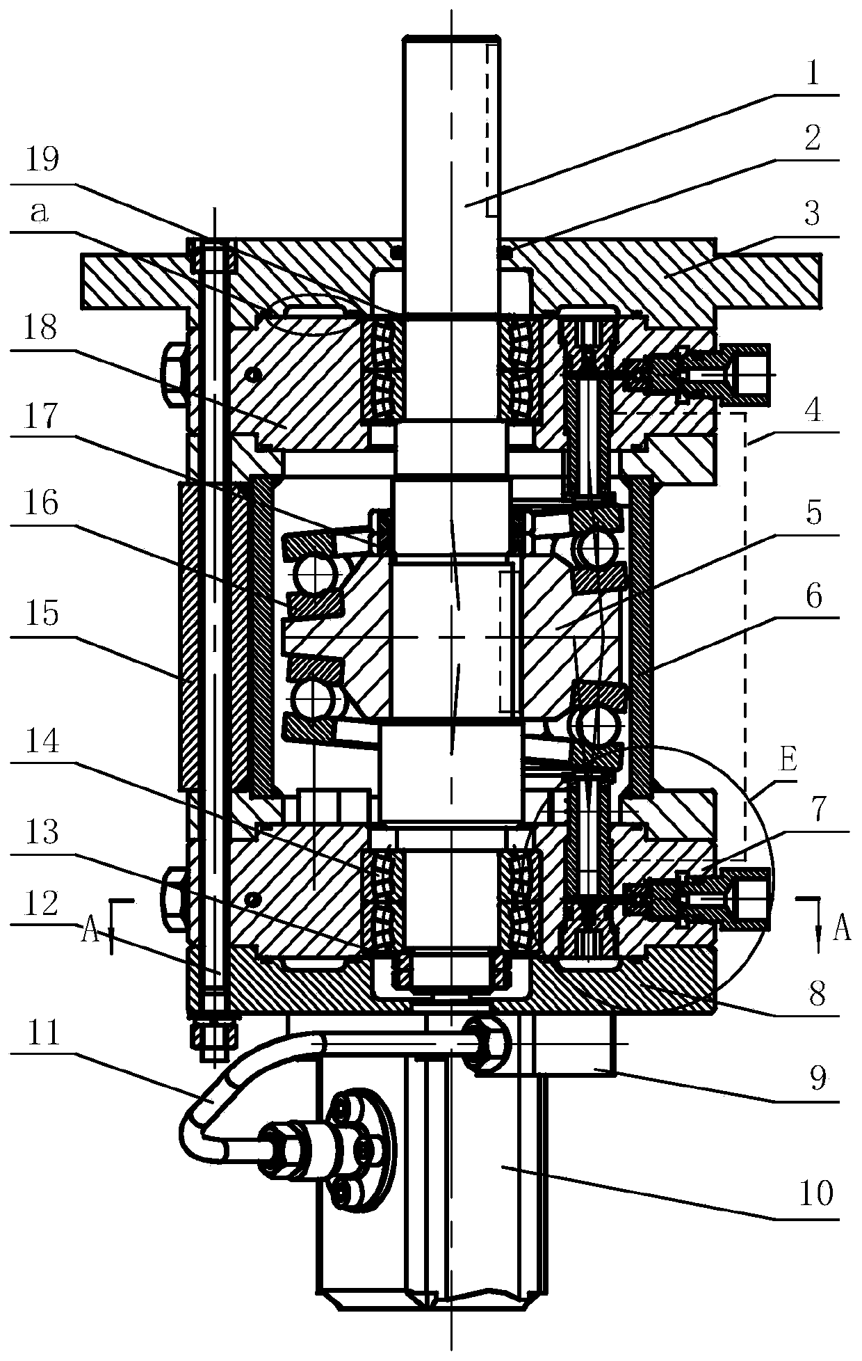
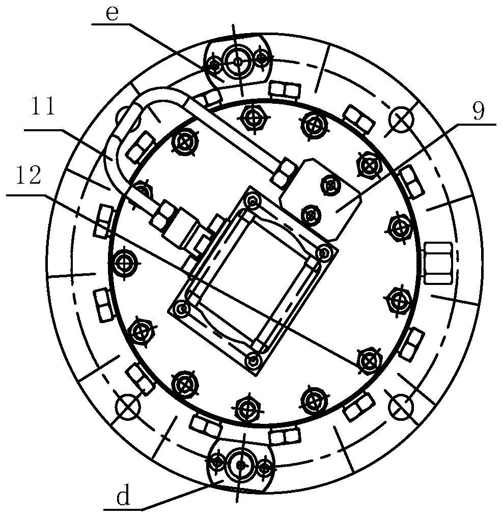
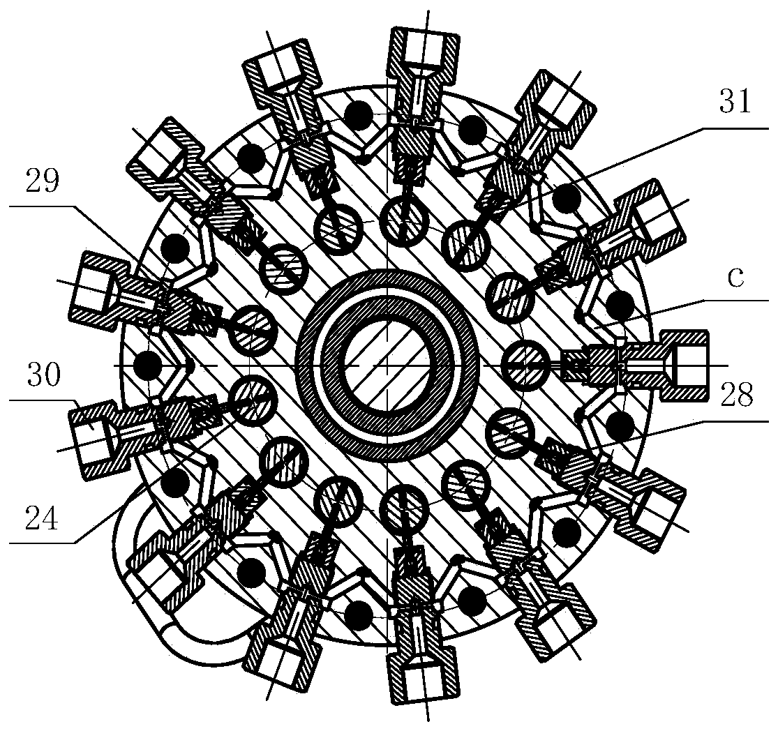
[0031] The present invention describes a new type of ultra-high pressure plunger pump, which includes a housing 6, which is relatively installed on the cylinder blocks at both ends of the housing 6, the main shaft 1 which runs through the cylinder and is placed inside the housing, and is installed coaxially with the main shaft 1 A double-sided balance swash plate 5 together; thrust ball bearings 16 are arranged on both sides of the double-side balance swash plate 5; a plurality of plungers squeezed by the thrust ball bearings 16 are evenly distributed radia...


PUM


Abstract

The invention discloses a novel ultrahigh pressure plunger pump, and belongs to the field of ultrahigh pressure hydraulic pumps. The pump comprises a shell, cylinder bodies oppositely arranged on thetwo ends of the shell, a spindle penetrating through the cylinder bodies and arranged in the shell, and a dual-side balance inclined disc coaxially mounted with the spindle; thrust ball bearings are arranged on the two sides of the dual-side balance inclined disc, multiple plunger assemblies with tops extruded by the thrust ball bearings are evenly distributed on the cylinder bodies in a manner ofsurrounding the spindle in the radial direction, oil suction openings of the plunger assemblies communicate with an oil outlet of a shuttle valve, one oil inlet of the shuttle valve communicates withan oil tank, the other oil inlet communicates with an oil supplementing pump, the oil supplementing pump is driven through the spindle, and an oil inlet of the oil supplementing pump communicates with the oil tank. According to the novel ultrahigh pressure plunger pump, the plunger cavities symmetric on the two sides are connected through a balance pipeline, axial imbalance force is effectively reduced, the number of plungers is two times that of a single row of plunger pump plungers, ultra-high pressure is ensured, and the flow of the plunger pump can be effectively increased.

Description

technical field [0001] The invention belongs to the field of ultra-high pressure hydraulic pumps, and in particular relates to a novel ultra-high pressure plunger pump, which can meet the requirements of small volume and large displacement, and can also balance axial unbalanced forces caused by processing errors and assembly errors. Background technique [0002] The ultra-high pressure of the hydraulic system has the advantages of reducing the installed weight, improving the level of equipment manufacturing, saving installed space, and realizing high system integration. It has a large demand in many fields such as aerospace, shipbuilding, metallurgy, and engineering machinery. One of the directions of development. At present, my country's ultra-high pressure hydraulic components mainly rely on imports. The main reason is that my country's basic research in this field is relatively weak, and there is a long-term lack of advanced innovative concepts and technical reserves. ...

Claims


Application Information

Patent Timeline
Patent Type & Authority Patents(China)
IPC IPC(8): F04B1/16F04B53/00F04B53/10F04B23/04
Inventor 张晋饶德才孙浩乾孔祥东
Owner YANSHAN UNIV
Why Eureka
Try Eureka