Wind driven generator braking equipment

A technology of wind power generators and braking equipment, applied in the control of wind power generators, wind power generators, wind power generation, etc., can solve the problems of damage to wind power generators, deceleration of wind power generator devices, and excessive speed of wind power generators The effect of reducing the failure rate, compact rhythm and simple structure

Active Publication Date: 2019-06-11
青岛百恒新能源技术有限公司
View PDF9 Cites 1 Cited by
  • Summary
  • Abstract
  • Description
  • Claims
  • Application Information

AI Technical Summary

Problems solved by technology

[0002] Fossil fuels will emit a large amount of harmful gases when they are used, and with the exploitation of fossil fuels this year, fossil fuels are exhausted, so countries are also actively seeking clean energy to replace fossil fuels, wind energy is widely used in my country as a clean energy Application, especially in the southeast coast of my country, but there are many typhoons in the southeast coast of my country. When the typhoon comes, the strong wind will drive the wind turbine to rotate too fast and damage the wind energy generator. Therefore, this part aims to design a wind energy generator. A device that brakes the generator when its speed reaches a certain value, thereby slowing down the wind turbine

Method used


Image

  • Wind driven generator braking equipment
  • Wind driven generator braking equipment
  • Wind driven generator braking equipment

Examples


Embodiment Construction

[0015] Combine below Figure 1-4 The present invention is described in detail, wherein, for the convenience of description, the orientations mentioned below are defined as follows: figure 1 The up, down, left, right, front and back directions of the projection relationship itself are the same.

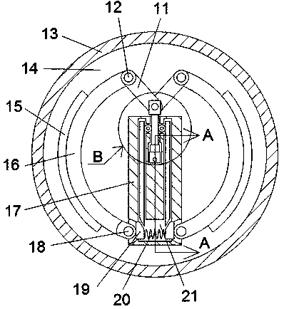
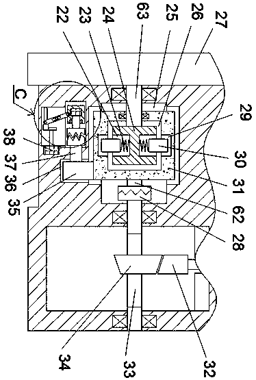
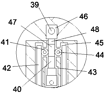
[0016] refer to Figure 1-4 , a wind power generator braking device of the present invention includes a brake drum 13 and a brake drum cavity 14 arranged in the brake drum 13, a fuselage 17 is arranged in the brake drum cavity 14, the The fuselage 17 is provided with a brake trigger chamber 43, and the brake trigger chamber 43 is provided with a central threaded rod 33 extending forward and backward, and the central threaded rod 33 is threadedly connected with a push block 34, and the push block 34 is offset A lifting block 32 is connected, and the lifting block 32 is fixedly connected with a lifting rod 40. The upper side of the brake triggering cavity 43 is provided with a rack and...


PUM


Abstract

The invention discloses wind driven generator braking equipment. The equipment comprises a drum brake and a drum brake cavity formed in the drum brake. A body is arranged in the drum brake cavity, andinternally provided with a braking trigger cavity. A center threaded rod extending front and back is arranged in the braking trigger cavity and connected with a push block in a screw thread fit mode.The push block is connected with a lifting block in an abutting mode. The lifting block is connected with a lifting rod in a stationary fit mode. A gear and rack engaging cavity is formed above the braking trigger cavity. The invention aims at designing a device capable of performing braking on a wind driven generator when the rotating speed of the wind driven generator reaches a certain value soas to reduce the speed of the wind driven generator device.

Description

technical field [0001] The invention relates to the technical field of wind power generator braking, in particular to a wind power generator braking device. Background technique [0002] Fossil fuels will emit a large amount of harmful gases when they are used, and with the exploitation of fossil fuels this year, fossil fuels are exhausted, so countries are also actively seeking clean energy to replace fossil fuels, wind energy is widely used in my country as a clean energy Application, especially in the southeast coast of my country, but there are many typhoons in the southeast coast of my country. When the typhoon comes, the strong wind will drive the wind turbine to rotate too fast and damage the wind energy generator. Therefore, this part aims to design a wind energy generator. A device that brakes the generator when its rotational speed reaches a certain value, thereby slowing down the wind turbine. Contents of the invention [0003] The technical problem to be solved ...

Claims


Application Information

Patent Timeline
Patent Type & Authority Applications(China)
IPC IPC(8): F03D7/00
CPCY02E10/72
Inventor 余丹丹
Owner 青岛百恒新能源技术有限公司
Why Eureka
Try Eureka