A method for installation, operation and maintenance of a stabilized pressure pilot drive valve
What is AI technical title?
AI technical title is built by PatSnap AI team. It summarizes the technical point description of the patent document.
A technology for driving valves and pilots, which is applied in the direction of valve operation/release devices, valve devices, and lift valves, and can solve problems such as complex structures, lateral displacement of diaphragms and valve stems, and increased manufacturing costs
Active Publication Date: 2020-07-07
CHANGSHA UNIVERSITY OF SCIENCE AND TECHNOLOGY
View PDF8 Cites 0 Cited by
Summary
Abstract
Description
Claims
Application Information
AI Technical Summary
This helps you quickly interpret patents by identifying the three key elements:
Problems solved by technology
Method used
Benefits of technology
Problems solved by technology
[0004] The pressure stabilizing valve in the prior art realizes the pilot drive through the pilot valve, and the pilot part is usually a cylinder. However, the cylinder in the prior art is often a moving part such as a piston, or two pistons are connected by a valve stem, and its function is single. Can realize "one in one out"
[0005] The existing technology also has a solution to "one in and one out", that is, it is set as a multi-way valve. However, the multi-way valve has three disadvantages: one is that the structure is complex and often requires multiple driving structures; the other is that although the driving source is reduced, However, in order to achieve multi-way, it is necessary to design a very complicated valve stem, with unevenness on the valve stem to match multiple valve ports; third, there is a lack of linkage effect between these channels
[0007] The pressure relief method in the prior art often uses a spring-loaded pressure relief valve. However, due to the structural characteristics of the cylinder itself, it is impossible to match the spring-loaded pressure relief valve to the structure of the cylinder; it must not only overcome structural problems, but also consider The air pressure inside the cylinder fluctuates, so it is technically very difficult to achieve
[0008] The cylinders in the prior art are often only connected with the intake end and the upper chamber, without considering the pressure of the outlet end, or setting sensors to realize the focus on the outlet end, thereby increasing the manufacturing cost
[0009] The pressure stabilizing valve in the prior art uses the upper chamber drive or auxiliary drive, but there are big problems in its guidance. The cooperation between the diaphragm and the valve stem will cause lateral displacement, and the long-term low matching degree will affect the service life after use.
Method used
Image
Click on the blue label to locate the original text in one second.
Reading with bidirectional positioning of images and text.
Examples
Embodiment Construction
[0038] The present invention will be further described below in conjunction with the accompanying drawings and embodiments.
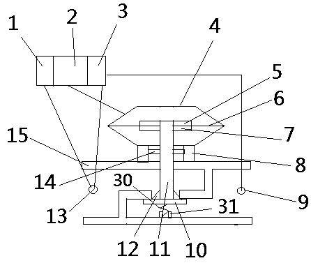
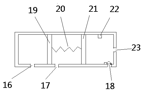
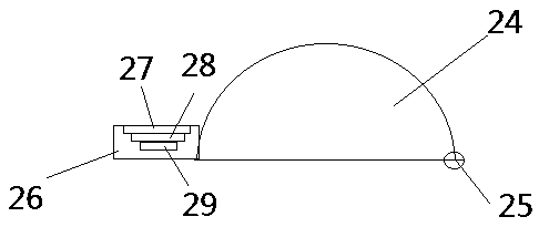
[0039] As shown in the figure: a method for installation, operation and maintenance of a stabilized pressure pilot drive valve. The stabilized pressure pilot drive valve includes a hexagonal upper valve body, an upper pressure plate, a diaphragm, a lower pressure plate, a column, a first through hole, a valve plate, and a valve. Rod, lower guide frame, second through hole, upper guide frame, lower valve body, lower spring, cylinder; wherein the cylinder includes left chamber, middle chamber, right chamber, air inlet, pressure regulating port, pressure relief port, right port , a left piston, an upper spring, a right piston, a limit post, a hemispherical cover, a pivot, and a connecting plate, wherein the connecting plate is provided with a receiving groove; the installation and maintenance method includes an installation method, a testing method, and an ...
PUM
Abstract
The invention discloses an installation and operation and maintenance method of a pressure-stabilizing pilot drive valve. The pressure-stabilizing pilot drive valve comprises a hexagonal upper valve body, an upper pressing plate, a diaphragm, a lower pressing plate, a stand column, a first through hole, a valve plate, a valve rod, a lower guide frame, a second through hole, an upper guide frame, alower valve body, a lower spring and an air cylinder, wherein the air cylinder comprises a left cavity, a middle cavity, a right cavity, an air inlet, a pressure regulating port, a pressure relief port, a right port, a left piston, an upper spring, a right piston, a limiting column, a hemisphere cover, a pivot and a connecting plate, and a containing groove is formed in the connecting plate. Theinstallation and operation and maintenance method comprises a mounting method, a testing method, and an operation method, wherein the testing method comprises the following steps that the pressure ofthe air inlet end of the valve is improved, the pressure above the diaphragm is improved, the valve plate is opened, the pressure of the air outlet end of the valve is tested, when the pressure of theair outlet end meets a preset value, after the pressure of the air inlet end is maintained for thirty minutes, the integrity of the diaphragm is detected, so that the pressure-bearing capability of the diaphragm under extreme pressure is tested.
Description
technical field [0001] The invention relates to the field of gas transportation control, in particular to a method for installation, operation and maintenance of a voltage stabilizing pilot drive valve. Background technique [0002] With the development of science and technology and the development of the economy, the requirements for fluid transportation are getting higher and higher. Hydraulic and pneumatic pipelines are widely used in industry, life and other fields. With the development of refinement, the requirements for pressure control and automation are also increasing. Higher and higher. Valves are important components in the field of pressure control, including pilot valves, pressure limiting valves, etc. Pressure limiting valves are also called safety valves. Drive components include electromagnetic drives, motor drives, manual drives, and automated drives. [0003] In actual use, there are the following problems: [0004] The pressure stabilizing valve in the ...
Claims
Application Information
Patent Timeline
Application Date:The date an application was filed.
Publication Date:The date a patent or application was officially published.
First Publication Date:The earliest publication date of a patent with the same application number.
Issue Date:Publication date of the patent grant document.
PCT Entry Date:The Entry date of PCT National Phase.
Estimated Expiry Date:The statutory expiry date of a patent right according to the Patent Law, and it is the longest term of protection that the patent right can achieve without the termination of the patent right due to other reasons(Term extension factor has been taken into account ).
Invalid Date:Actual expiry date is based on effective date or publication date of legal transaction data of invalid patent.
Patent Type & AuthorityPatents(China)
IPC IPC(8): F16K31/365F16K1/00
CPCF16K1/00F16K31/365
Inventor伍文广胡林唐洪亮严旭
OwnerCHANGSHA UNIVERSITY OF SCIENCE AND TECHNOLOGY

