Trigger tool

A trigger and blade technology, applied in the field of trigger knives, can solve the problems of short blade extension distance, limit the use range of trigger knives, and short stroke of the knife, so as to achieve the effect of easy starting

Active Publication Date: 2019-09-13
广州宝瑰贸易有限公司
View PDF6 Cites 1 Cited by
  • Summary
  • Abstract
  • Description
  • Claims
  • Application Information

AI Technical Summary

Problems solved by technology

[0006] In order to consider the user's experience, so that the user can pull the trigger without spending a lot of effort, the above two kinds of trigger knives have a short stroke, and the short stroke will result in a short distance for the blade to protrude, thus limiting The scope of use of the trigger knife

Method used


Image

  • Trigger tool
  • Trigger tool
  • Trigger tool

Examples


Embodiment Construction

[0030] Below, the present invention will be further described in conjunction with the accompanying drawings and specific implementation methods. It should be noted that, under the premise of not conflicting, the various embodiments described below or the technical features can be combined arbitrarily to form new embodiments. .

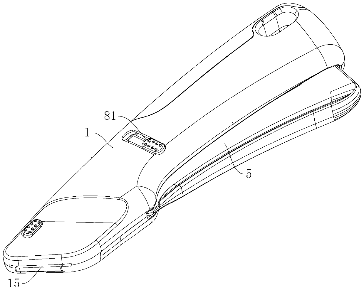
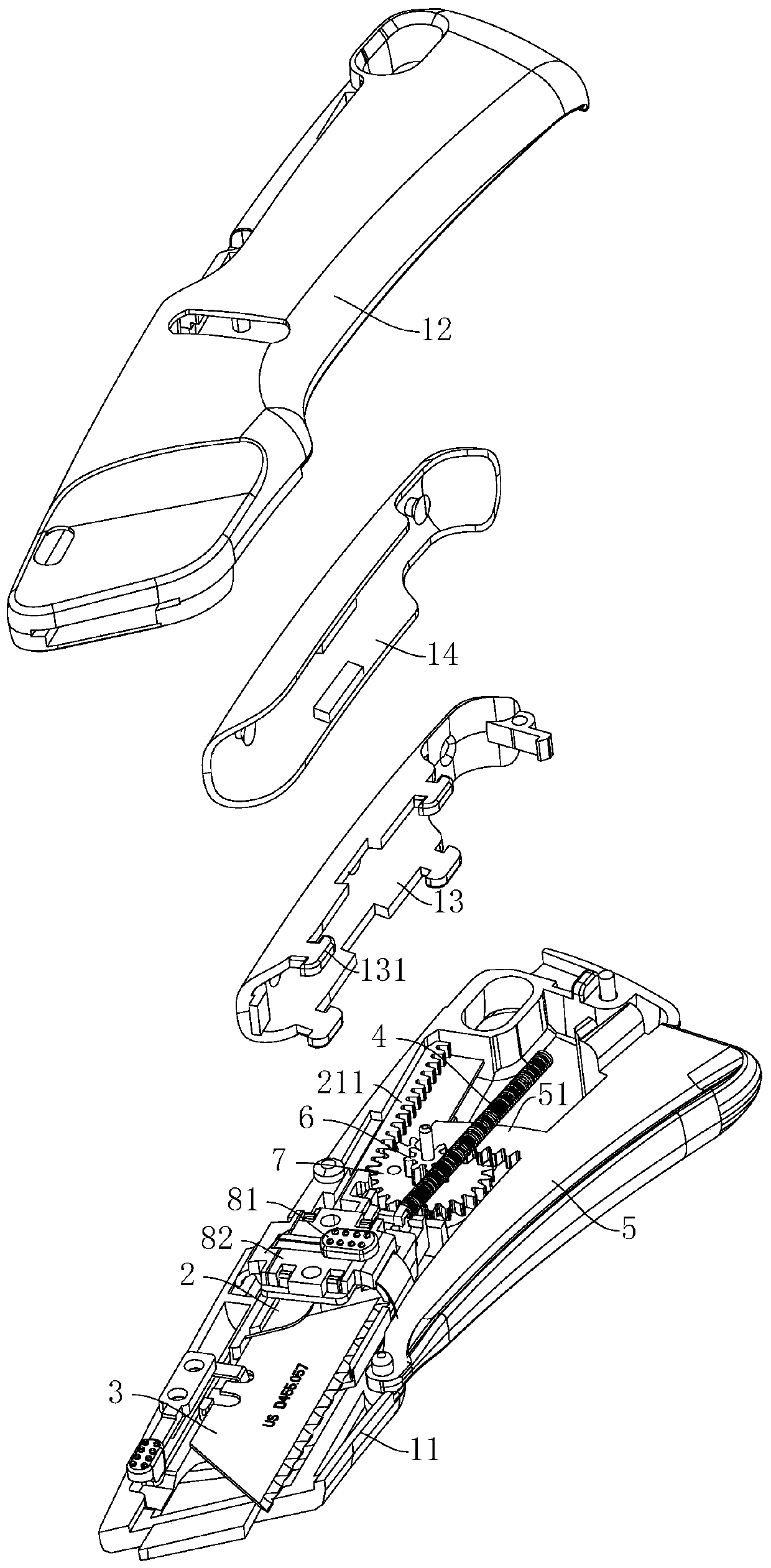
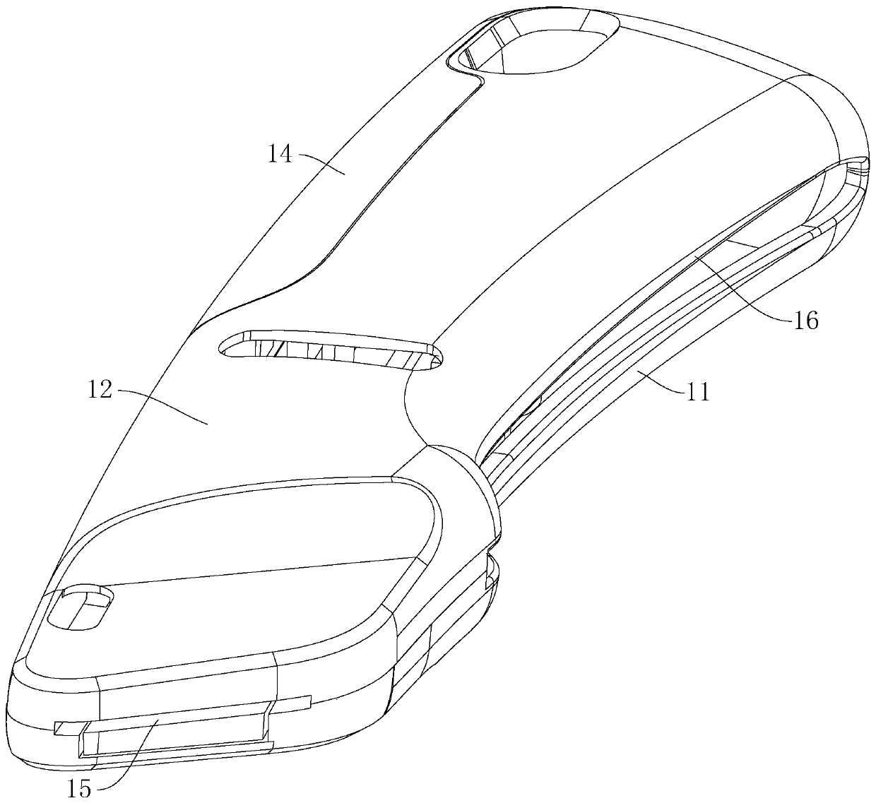
[0031] see Figure 1-Figure 2 , shows a kind of trigger 5 knife of a preferred embodiment of the present invention, and this trigger 5 knife comprises knife body 1, knife rest 2, blade 3, elastic member, trigger 5, transmission mechanism and block 81, wherein, knife rest 2. The blade 3, the elastic member and the transmission mechanism are all located in the inner cavity of the blade body 1, and the blade holder 2 is slidably connected with the blade body 1, so that the blade 3 can extend out of the blade body 1 along the first notch 15 of the blade body 1 or retract. Back in the knife body 1, the blade 3 is connected with the knife holder 2, the elas...


PUM


Abstract

The invention discloses a trigger tool. The trigger tool comprises a tool body, a tool rest, a tool blade, an elastic part, a trigger, a transmission mechanism and a baffle plate, wherein the tool rest is sidably connected with the tool body; the tool blade is connected with the tool rest; the elastic part is used for providing elastic force for the tool blade to retract in a inner cavity of the tool body; the trigger is rotatably arranged on the tool blade to be capable of moving in the tool body; part of the trigger is exposed out of the tool body; the transmission mechanism comprises a first rack, a first wheel gear, a second wheel gear and a second rack; the first wheel gear and the second wheel gear are both in pivotal connection with the tool body; the center axis of a rotating shaftis perpendicular to the sliding direction of the tool rest; the first rack is arranged on the trigger and is engaged with the first wheel gear; the second rack is arranged on the tool rest and is engaged with the second wheel gear; the extending direction of the second rack is the same as the sliding direction of the tool rest; a groove is formed in the tool rest; the extending direction of the groove is the same as the extending direction of the tool rest; and when the tool blade extends in place, the baffle block abuts against the sidewall of the groove. The trigger tool is easy to draw andthe drawing distance is longer.

Description

technical field [0001] The invention relates to the technical field of hand-held safety knives, in particular to a trigger knife. Background technique [0002] The trigger knife is a kind of knife among hand-held safety knives. Its blade can be retracted into the knife body, and its blade can extend out of the knife body when in use, thus improving the safety of the trigger knife. [0003] For example, a safety cutting knife disclosed by the patent application number CN201010230575.4 specifically includes a housing, a detachable blade protective sleeve placed at the end of the housing, and a blade fixedly connected to the rotating knife rest. The two ends of the tension spring are respectively connected to the housing and the slider, and the two ends of the tension spring are respectively connected to the housing and the sliding knife holder. One end of the trigger is connected to the housing through the fulcrum E, and the other end of the trigger can move up and down around...

Claims


Application Information

Patent Timeline
Patent Type & Authority Applications(China)
IPC IPC(8): B26B1/08B26B5/00
CPCB26B5/001B26B5/003
Inventor 刘家杰
Owner 广州宝瑰贸易有限公司
Why Eureka
Try Eureka