Pit-type drip irrigation device

A technology of pit and irrigator is applied in the field of agricultural irrigation, which can solve the problems of increased dissipation and high flow index, and achieve the effects of reducing flow index, long service life and simple operation.

Pending Publication Date: 2019-09-17
KUNMING UNIV OF SCI & TECH
View PDF4 Cites 0 Cited by
  • Summary
  • Abstract
  • Description
  • Claims
  • Application Information

AI Technical Summary

Problems solved by technology

Labyrinth channel is the classic structure of current drip irrigation channel. In order to optimize its current problem of high flow index, the present invention builds a sudden expansion shunt, rapid Drip irrigation emitter with a new type of pit flow channel that increases dissipation such as transfer and confluence

Method used


Image

  • Pit-type drip irrigation device
  • Pit-type drip irrigation device
  • Pit-type drip irrigation device

Examples


Embodiment 1

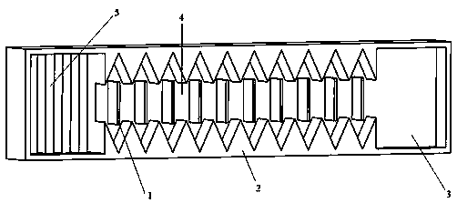
[0025] like Figures 1 to 7 As shown, the pit type drip irrigation device includes a pit type drip irrigation emitter 2 and a pipeline device;

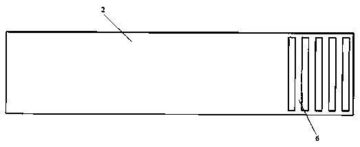
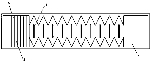
[0026] The pit type drip irrigation emitter 2 includes a water outlet 3, a pit flow channel 4, a water inlet 5 and a filter plate 6, and the pit flow channel 4 includes a plurality of symmetrical pit flow channel unit structures, each pit flow channel The unit structure includes a vertically symmetrical toothed structure and a water baffle 1; the pipeline device includes a pipeline 7 and a drop opening 8;

[0027] Several pit-type drip irrigation emitters 2 are evenly arranged in the inner wall of the pipeline 7, each pit-type drip irrigation emitter 2 is a cuboid structure, and each pit-type drip irrigation emitter 2 is located on the top side of the pipeline 7. There is a filter plate 6, the bottom of the filter plate 6 is provided with a through water inlet 5 to the bottom surface of the pit type drip irrigation emitter 2, and the...


PUM


Abstract

The invention relates to a pit-type drip irrigation device, and belongs to the technical field of agricultural irrigation. The pit-type drip irrigation device comprises a pit-type drip irrigation emitter and a pipeline device, wherein the pit-type drip irrigation emitter comprises a water outlet, a pitting flow channel, a water inlet and a filter plate, the pitting flow channel comprises a plurality of symmetrical pitting flow channel unit structures, each pitting flow channel unit structure comprises a tooth-shaped structure and a water baffle which are vertically symmetrical; the pipeline device comprises a pipeline and a drip port. The device is simple to operate, saves time and labor, and has the advantages of integral selectivity, cost saving and high efficiency.

Description

technical field [0001] The invention relates to a pit type drip irrigation device, which belongs to the technical field of agricultural irrigation. Background technique [0002] With the gradual improvement of agricultural modernization in our country, drip irrigation has become the most effective water-saving irrigation method to solve arid and water-scarce areas. The hydraulic performance of drip irrigation emitters has always been a hot research issue, and its hydraulic performance is mainly determined by the structure of the flow channel. , many scholars at home and abroad have proposed to improve the hydraulic performance of the runner by optimizing the structure of the runner itself. The hydraulic performance of the runner is expressed by the flow index, which reflects the flow characteristic of the emitter and the sensitivity of the flow rate to the pressure head. Labyrinth channel is the classic structure of current drip irrigation channel. In order to optimize its c...

Claims


Application Information

Patent Timeline
Patent Type & Authority Applications(China)
IPC IPC(8): A01G25/02
CPCA01G25/023Y02A40/22
Inventor 张立翔徐天宇
Owner KUNMING UNIV OF SCI & TECH
Why Eureka
Try Eureka