Jet flow pulse drip irrigation emitter and drip irrigation method

A technology of irrigators and pulse generators, which is applied to botany equipment and methods, watering devices, climate change adaptation, etc., and can solve the problems affecting the long-term operation and use of pulse drip irrigation systems, sensitivity, reliability decline, and pulse generators. Complicated structure and other problems, to achieve the effect of increasing anti-clogging ability, improving transportation capacity, and low manufacturing cost

Inactive Publication Date: 2013-07-17
JIANGSU UNIV
View PDF2 Cites 0 Cited by
  • Summary
  • Abstract
  • Description
  • Claims
  • Application Information

AI Technical Summary

Problems solved by technology

[0004] Existing pulse drip irrigation utilizes the expansion and reset of elastic materials such as rubber, plastic, and springs to achieve the purpose of pulse water flow; drip irrigation systems generally run for a long time, and elastic materials are prone to fatigue during long-term, high-frequency frequent reciprocating operations , or even damage; the pulse frequency depends on the stiffness and initial compression of the elastic material. Long-term operation will lead to changes in the stiffness and elastic modulus of the elastic material, and the elasticity will decrease. Sensitivity and reliability will decrease to varying degrees, thus affecting pulse drip irrigation. Long-term operation and use of the system; the use of elastic materials will inevitably increase the structural complexity of the pulse generator, and put forward higher requirements for mechanical sealing, manufacturing precision, reliability and durability

Method used


Image

  • Jet flow pulse drip irrigation emitter and drip irrigation method
  • Jet flow pulse drip irrigation emitter and drip irrigation method
  • Jet flow pulse drip irrigation emitter and drip irrigation method

Examples


Embodiment 1

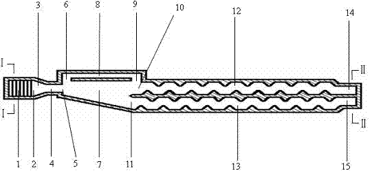
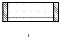
[0023] refer to figure 1 , figure 2 , image 3 , Figure 4 , the bottom of the water inlet tank 1 is provided with a filter window 16, and the end of the water inlet tank 1 is connected to the inlet 2 of the jet pulse generator; the jet pulse generator is composed of the inlet 2 of the jet pulse generator, the contraction section 3, the diversion section 4, the jet nozzle 5, and the control port 6. Jet space 7, control channel 8, signal port 9, straight jet outlet 10 and oblique jet outlet 11, the front end of the jet pulse generator is the jet pulse generator inlet 2, and the front of the jet pulse generator inlet 2 is connected to the water inlet tank 1 , the back of the jet pulse generator inlet 2 is connected to an inverted trumpet-shaped constriction section 3 with a large front and a small rear. The constriction section 3 is connected to a rectangular diversion section 4. The rectangular diversion section 4 is connected to a jet nozzle 5. A control port 6 is set on t...

Embodiment 2

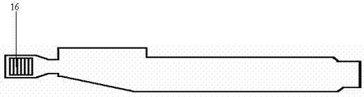
[0026] refer to Figure 5 , figure 2 , Figure 6 , Figure 7 , the basic structural features are similar to Embodiment 1, and the difference from Embodiment 1 is that the water outlet groove is connected to form a jet pulse drip irrigation emitter with only one water outlet, and the water outlet groove 17 is located in the straight jet flow channel 12 and the oblique jet flow channel 13 Connect the ends of the two flow channels so that the two flow channels share one outlet.


PUM


Abstract

The invention belongs to the technical field of agricultural water-saving irrigation, relating to a drip irrigation emitter and especially to a jet flow pulse drip irrigation emitter and a drip irrigation method. The jet flow pulse drip irrigation emitter is composed of a water inlet groove, a jet flow pulse generator, a flow channel and a water outlet groove, the water inlet groove is provided with a filtering window and is communicated with the jet flow pulse generator, the jet flow pulse generator is communicated with the flow channel, and the water outlet groove is situated on the tail end of the flow channel. Jet flow control technology is used for driving water stream to intermittently flow in two flow channels so as to realize a continuous pulse process, form strong turbulent motion and impact water stream in the flow channels and reinforce the anti-clogging capability and irrigation uniformity of the drip irrigation emitter. The jet flow pulse drip irrigation emitter omits such elastomer structures of the current drip irrigation pulse generator, such as rubber, plastic film and spring, and the like, and the jet flow pulse drip irrigation emitter has simple structure, good reliability and strong durability, so that the jet flow pulse drip irrigation emitter can be extensively suitable for the irrigation demands of filed crops, vegetables and forest and fruit industry.

Description

technical field [0001] The invention belongs to the technical field of agricultural water-saving irrigation, and relates to a drip irrigation dispenser, in particular to a jet pulse drip irrigation dispenser and a drip irrigation method. Background technique [0002] Pulse drip irrigation has the characteristics of strong anti-clogging performance and high irrigation uniformity, and has been widely concerned and applied by countries all over the world; the pulse drip irrigation system generates continuous pulse water flow through the cycle of pulse generator water storage and pulse, and its working process is generally by water filling. Pressurization and water outlet decompression are composed of two independent stages, and the two stages are automatically reciprocated, so that the water flows intermittently from the drip irrigation emitter at a certain pulse frequency, realizing the pulse drip irrigation method. [0003] The pulse generator is the core device that turn...

Claims


Application Information

Patent Timeline
Patent Type & Authority Patents(China)
IPC IPC(8): A01G25/02
CPCY02A40/22
Inventor 王新坤
Owner JIANGSU UNIV
Why Eureka
Try Eureka