Vehicular status signal system

A vehicle status and signal system technology, applied in the field of vehicle signal lighting system, can solve the problems of preventing hijacking and abuse of vehicles, etc.

Inactive Publication Date: 2006-12-27
龚立新
View PDF1 Cites 26 Cited by
  • Summary
  • Abstract
  • Description
  • Claims
  • Application Information

AI Technical Summary

Problems solved by technology

Chinese Patent Publication No. CN2397001Y, titled "Automatic Vehicle Anti-Rear-Collision Warning Device", attempts to challenge this subject. When you need to brake and your foot is loose on the accelerator, the acceleration sensor will generate an output signal due to sudden deceleration. After amplified processing, the warning light can be turned on before the foot brakes to achieve the purpose of brake warning.” Claiming to solve the problem of brake warning, Little do they know that this is a practice of abusing the brake warning, and occasionally it may be wrong several times, but it will bring more brake danger
They are only limited to anti-theft alarms and cannot be used to prevent car hijacking. In particular, there is no device that can be used to prevent car theft and car hijacking, and can be used for driving safety, providing drivers with double insurance for life and property.

Method used


Image

  • Vehicular status signal system
  • Vehicular status signal system
  • Vehicular status signal system

Examples


Embodiment 1

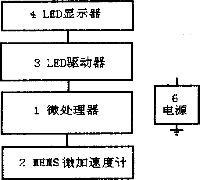
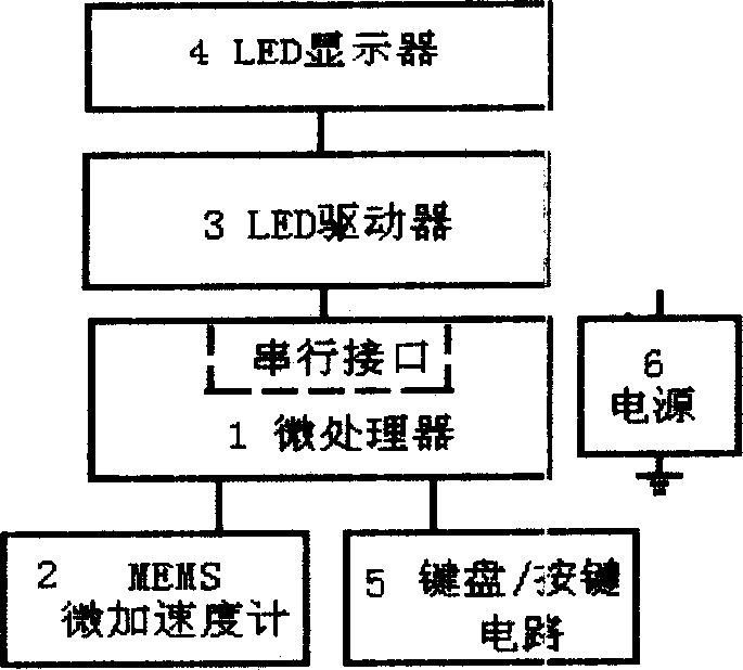
[0135] Embodiment 1: as figure 1 As shown in Figure 5, microprocessor 1 uses AT89C2051 microcontroller, micro accelerometer 2 uses micro accelerometer MXD2020 with MEMS dual-axis digital signal output, LED driver 3 uses 8-bit constant current drive integrated circuit HM63595, and HM68595 consists of an 8-bit string In-parallel-out, serial-in-serial-out shift register, 8-bit data latch and 8-bit constant current driver are composed of three main parts. The shift register receives serial input data, outputs serial data, and provides parallel data to the latch. Shift registers and latches have independent clock inputs CLOCK. The LED display 4 adopts dual primary color LEDs. The vehicle dynamic / static state signal collected automatically by MXD2020 is output from Doutx and Douty ports to both ends of INT0 and INT1 of AT89C2051 single-chip microcomputer in the form of digital pulse width duty ratio, and the pulse width is measured by interrupt mode to complete the vehicle dynami...

Embodiment 2

[0136] Embodiment 2: as Figure 2-2 As shown in Figure 6, the basic principle of this example is the same as that of Embodiment 1. The LED driver 3 uses a dedicated integrated drive circuit HM62726. And 16-bit driver consists of three main parts. The shift register receives serial input data, outputs serial data, and provides parallel data to the latch. The shift register and the latch have independent clock input terminals CLK, and there is an asynchronous reset terminal for the shift register. The output current value of the driver can be controlled by the external resistor R12 to achieve constant current output. The LED display 4 also adopts dual primary color LEDs.

[0137] The difference is that the microprocessor 1 adopts the P87LPC76X single-chip microcomputer, and the micro-accelerometer 2 adopts the micro-accelerometer ADXL202 with MEMS dual-axis digital signal output. Output from Doutx and Douty ports to both ends of INT0 and INT1 of P87LPC76X single-chip microco...

Embodiment 3

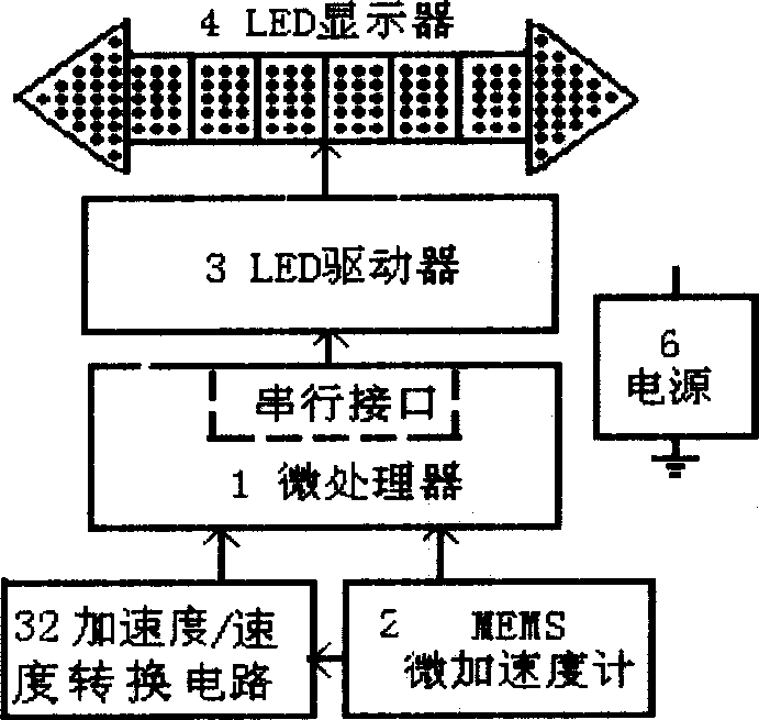
[0138] Embodiment 3: as figure 1 As shown in FIG. 7 , the basic principle of this example is the same as that of Example 1, and the LED display 4 also adopts dual primary color LEDs. The difference is that microprocessor 1 adopts PCI16C71X single-chip microcomputer, micro accelerometer 2 adopts micro accelerometer ADXL311 with MEMS dual-axis analog signal output, LED driver 3 adopts triode or FET drive circuit, and ADXL311 automatically collects the dynamic / static state of the vehicle The signal is output as an analog signal from the Xout and Yout ports to the two ends of AN0 and AN1 of the PCI16C71X single-chip microcomputer, and the internal A / D conversion of the single-chip microcomputer is used to complete the vehicle dynamic / static state signal input, and then the result is output through the PCI16C71X analysis and processing program and passed through 8 The bit parallel port is output to the triode drive circuit, thereby driving the dual-color LED display, and displayin...


PUM


Abstract

A vehicle state signal system is aimed to provide early-warnings to a traffic accident and a vehicle robbery and theft. The system is composed of a microprocessor, a LED driver, a LED display, a MEMS micro-accelerometer, an acceleration / speed converter, a keyboard / key circuit and a power supply, so that the system can automatically display the speed and provide early-warnings to the driver. The high brightness LED tricolor dynamic display can generate difference obvious color and visual effects to win an early-warning time about 0.8~1 second. The invention can improve the vehicle running and parking safety, reduce collision accidents, and is easy to install.

Description

(1) Technical field [0001] The invention relates to a vehicle signal lighting system, in particular to a vehicle state signal system, which belongs to the category of vehicle signal lights. (2) Background technology [0002] For the drivers and passengers, the safety of the vehicle and the prevention of robbery after parking, involving life and property are always the first. The traditional vehicle signal lighting system mainly includes turn signals, tail lights, reversing lights and brake lights, etc. Among them, there are many problems with the brake lights, which have not been solved for a long time. They are controlled by switches, which are manually operated by the driver to light up the lights by stepping on the pedal or pressing the switch. This control method has a slow response speed and often wastes a lot of valuable warning time. The traditional vehicle signal light system is the driver's The operating light signal system is not the light signal system of the veh...

Claims


Application Information

Patent Timeline
Patent Type & Authority Applications(China)
IPC IPC(8): B60Q1/26
Inventor 龚立新龚青
Owner 龚立新
Why Eureka
Try Eureka