Oscillating drip irrigation emitter

A technology of irrigation and water tank, applied in watering device, spray device, climate change adaptation and other directions, can solve the problems of high oscillating pulse frequency of positive feedback oscillating pulse generator, difficult to grasp design and application, etc., to achieve efficient energy dissipation effect, increase anti-clogging ability, uniform dripping effect

Inactive Publication Date: 2014-12-03
JIANGSU UNIV
View PDF4 Cites 0 Cited by
  • Summary
  • Abstract
  • Description
  • Claims
  • Application Information

AI Technical Summary

Problems solved by technology

Positive feedback oscillating pulse generator has high oscillating pulse frequency, which is difficult to master in design and application

Method used


Image

  • Oscillating drip irrigation emitter
  • Oscillating drip irrigation emitter
  • Oscillating drip irrigation emitter

Examples


Embodiment 1

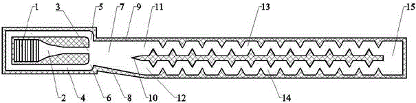
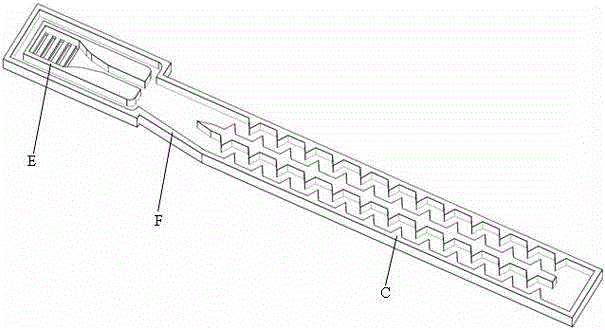
[0021] Embodiment 1: refer to figure 1 and image 3 The oscillating drip irrigation emitter shown in this embodiment is composed of a water inlet tank E, an oscillating element F and a flow channel body C. The water inlet trough E is provided with a filter window 1 and communicates with the inlet of the oscillating element F, and the outlet of the oscillating element F is connected to the flow channel body C. The inlet of channel body C is connected; the oscillating element F is composed of nozzle 3, control channel 4, control port I5, control port II6, jet space 7, inclined side wall 8, straight side wall 9, splitter splitter 10, straight jet outlet 11. Composed of oblique jet outlet 12; the jet space 7 of the oscillating element F is an asymmetric structure of a right-angled trapezoid, the right-angled side of the trapezoid is the straight side wall 9, and the hypotenuse is the inclined side wall 8; the front end of the oscillating element F is the nozzle 3. Control port Ⅰ5...

Embodiment 2

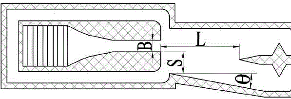
[0026] refer to Figure 4 , Figure 6 , the basic structural features are similar to those of Embodiment 1, and the difference from Embodiment 1 is that the top of the splitter 10 is in a concave arc shape, and the two flow channels are arranged in a U-shape. 13 communicates with the straight jet outflow tank 17, and the oblique jet flow channel 14 communicates with the oblique jet outflow tank 16. The size of the oscillating element F varies, refer to Figure 5 , the nozzle width B is 0.8mm, the ratio of the headroom S on the straight jet side to the nozzle width B is 1:1.0, the ratio of the headroom S on the oblique jet side to the nozzle width B is 1:1.9, the split distance L and the nozzle width The ratio of B is 1:6.8, the opening angle θ is 10.5°, and the ratio of nozzle depth to nozzle width B is 1:1.2.


PUM


Abstract

The invention discloses an oscillating drip irrigation emitter which consists of a water inlet channel, an oscillation element and a runner body, wherein the water inlet channel is provided with a filter window and communicated with an inlet of the oscillation element; the oscillation element is of an asymmetric structure; an outlet of the oscillation element is communicated with an inlet of the runner body; and a water outlet channel is arranged at the tail end of the runner body. According to the Coanda and negative-pressure control oscillation technology and the characteristic of the asymmetric structure, the water flow is driven to flow intermittently in two runners to realize a continuous oscillation and pulse process and form a strong turbulence and impact water flow in the runners as well as enhance the anti-blocking ability and irrigation uniformity of the irrigation emitter. According to the invention, elastic structures such as rubber, plastic films, springs and the like of the existing drip irrigation pulse generator are saved, and the oscillating drip irrigation emitter has the characteristics of simple structure and high reliability and durability. The material and processing equipment and method of the existing drip irrigation emitter can be adopted, the oscillating drip irrigation emitter is subjected to once injection molding, the processing technology is simple, the manufacturing cost is low, and the oscillating drip irrigation emitter is convenient to mount and use. The oscillating drip irrigation emitter disclosed by the invention can be widely applied to the irrigation of the field crops, vegetables, forestry and fruit growing and the like.

Description

technical field [0001] The invention belongs to the technical field of agricultural water-saving irrigation, and relates to a drip irrigation dispenser, in particular to an oscillating drip irrigation dispenser. Background technique [0002] Pulse drip irrigation has the characteristics of strong anti-clogging performance and high irrigation uniformity, and has been widely concerned and applied by countries all over the world. The pulse generator is the core device that turns the pressure water flow in the drip irrigation system into a pulse water flow. Most of the existing pulse generators have an elastic cavity that can be expanded and reset. The elastic cavity is made of elastic materials such as rubber, plastic diaphragms or springs. The structure uses the expansion and reset of elastic materials such as rubber, plastic, and springs to achieve the purpose of pulsating water flow. In the stage of water filling and pressurization, the pressure water flow enters the el...

Claims


Application Information

Patent Timeline
Patent Type & Authority Patents(China)
IPC IPC(8): B05B1/34A01G25/02
CPCY02A40/22
Inventor 王新坤
Owner JIANGSU UNIV
Why Eureka
Try Eureka