Polishing device for sheet metal parts

A polishing device and a technology for sheet metal parts, applied in the field of sheet metal parts, can solve the problems of poor polishing effect, poor debris and dust treatment, etc., and achieve the effect of improving convenience, convenient centralized processing, and easy to use

Pending Publication Date: 2019-10-29
合肥高科科技股份有限公司
View PDF0 Cites 1 Cited by
  • Summary
  • Abstract
  • Description
  • Claims
  • Application Information

AI Technical Summary

Problems solved by technology

[0003] However, the polishing effect of large polishing devices for small sheet metal parts is not very good, and small polishing devices are needed for polishing, and the debris and dust generated during the polishing process are not very effective. Therefore, we propose a sheet metal Polishing device for parts

Method used


Image

  • Polishing device for sheet metal parts
  • Polishing device for sheet metal parts

Examples


Embodiment 1

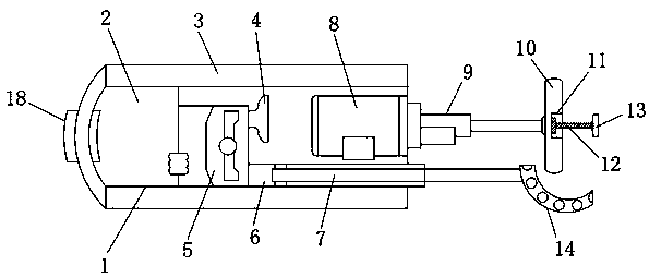
[0020] Such as figure 1 As shown, a polishing device for sheet metal parts includes a handle 1, a motor 8 is clamped at one end of the handle 1, an electric cylinder 9 is installed at one end of the handle 1, the output shaft of the motor 8 is clamped with the electric cylinder 9, and one end of the electric cylinder 9 A polishing disc 10 is clamped, and the interior of the polishing disc 10 is inlaid with a groove 11, and the inner wall of the groove 11 is inlaid with an air pressure rod 12. One end of the air pressure rod 12 is fixedly connected to the small hole polishing disc 13, and the connecting pipe 6 is located at the bottom of the handle 1 to collect dust. Both the chamber 2 and the suction port 4 are located inside the handle 1, and a valve 18 is installed on one side of the dust collection chamber 2.

[0021] In this embodiment, by setting electric cylinder 9, air pressure rod 12 and small hole polishing disc 13, it is convenient for people to polish small sheet me...

Embodiment 2

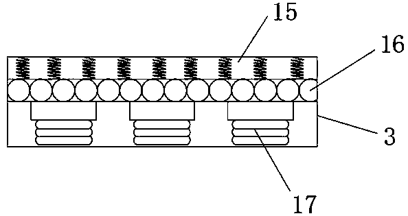
[0023] Such as Figure 1-2 As shown, a small exhaust fan 5 is installed at one end inside the handle 1, one side of the small exhaust fan 5 is fixedly connected to the dust collection chamber 2, and the other end of the small exhaust fan 5 is installed with an air suction port 4 and a connecting pipe 6, and the connecting pipe 6 is internally slidably connected Sleeve pipe 7, one end of socket pipe 7 is welded with arc-shaped suction pipe 14, which is located on one side of polishing disc 10, rubber shock-absorbing pad 3 is sleeved on the outside of handle 1, and the inside of rubber shock-absorbing pad 3 is filled with The spring layer 15, the elastic ball layer 16 and the air cushion shock absorber 17, the elastic ball layer 16 is bonded to the bottom of the spring layer 15, and the air cushion shock absorber 17 is bonded to the bottom of the elastic ball layer 16.

[0024] In this embodiment, by arranging a small exhaust fan 5, a connecting pipe 6, a socket pipe 7 and an ar...


PUM


Abstract

The invention discloses a polishing device for sheet metal parts. The polishing device comprises a handle, wherein a motor is clamped at one end inside the handle, an electric cylinder is installed atone end of the handle, a motor output shaft is connected with the electric cylinder in a clamped mode, one end of the electric cylinder is connected with a polishing disk in a clamped mode, and a groove is inlaid in the polishing disk. According to the polishing device, through the arrangement of the electric cylinder, an air pressure rod and a small-hole polishing disk, people can conveniently polish a sheet metal small part, and a through hole and small hole of the sheet metal part, the device is small and flexible, and the convenience in use of the polishing device is effectively improved;through the arrangement of a small suction fan, a connecting pipeline, a sleeving connecting pipe and an arc dust suction pipe, chippings, dust and the like generated by polishing work are effectively sucked, and the human body is prevented from sucking in the chippings, the dust and the like; and through the arrangement of a spring layer, an elastic ball layer and an air cushion damper, the vibration during working of the device is effectively reduced, the inconvenient operation of hands due to vibration is avoided, and the device is suitable for being widely popularized and used.

Description

technical field [0001] The invention relates to a sheet metal part, in particular to a polishing device for a sheet metal part. Background technique [0002] Sheet metal parts are thin-plate hardware parts, that is, parts that can be processed by stamping, bending, stretching, etc. A general definition is - parts whose thickness does not change during processing, corresponding to castings, forgings , machining parts, etc. For example, the outer iron shell of a car is a sheet metal part, and some kitchen utensils made of stainless steel are also sheet metal parts. [0003] However, the polishing effect of large polishing devices for small sheet metal parts is not very good, and small polishing devices are needed for polishing, and the debris and dust generated during the polishing process are not very effective. Therefore, we propose a sheet metal Parts with polishing device. Contents of the invention [0004] The main purpose of the present invention is to provide a poli...

Claims


Application Information

Patent Timeline
Patent Type & Authority Applications(China)
IPC IPC(8): B24B29/02B24B41/00B24B55/10B24B27/00B24B47/12B24B47/14B24B55/02B24B23/02
CPCB24B23/02B24B27/0076B24B29/02B24B41/007B24B47/12B24B47/14B24B55/02B24B55/10
Inventor 胡翔
Owner 合肥高科科技股份有限公司
Why Eureka
Try Eureka