Unstacker

A technology of unstacking machine and lifting mechanism, which is applied in the direction of unstacking of objects, conveyors, stacking of objects, etc., which can solve the problems of inconvenience, low efficiency of unstacking, increased workload and labor intensity, etc., to improve safety performance, improve the efficiency of unstacking, and save time

Pending Publication Date: 2019-11-22
山东腾阳智能装备有限公司
View PDF0 Cites 0 Cited by
  • Summary
  • Abstract
  • Description
  • Claims
  • Application Information

AI Technical Summary

Problems solved by technology

[0002] In production, in order to facilitate the transportation of material bags, the material bags are usually stacked on the pallet with a palletizer, which is convenient for transshipment with a forklift. When in use, the stacked material bags need to be de-stacked. In the traditional manual method, the working process is to use manual handling to grab, and then put it on the conveying equipment. Due to personnel management and increased output, the workload and labor intensity increase, and the efficiency of unstacking is low, which is inconvenient in actual production.

Method used


Image

  • Unstacker
  • Unstacker
  • Unstacker

Examples


Embodiment 1

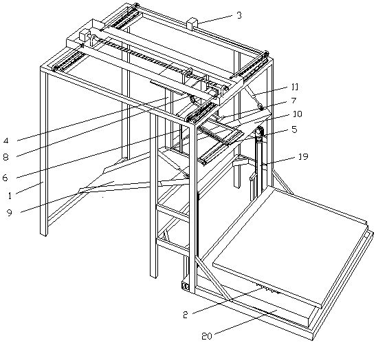
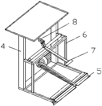
[0027] Embodiment 1: A depalletizer, comprising a depalletizing device and an empty pallet transfer device. Such as figure 1 Said, the destacking device comprises a first support 1 and a second elevating mechanism 19 located on one side of the first support 1, the first support 1 comprises two vertical and parallel rectangular plates, the rectangular The plates are connected by beams. The lifting device includes a second lifting mechanism 19 and a supporting plate 20 fixed to the movable end of the second lifting mechanism 19. The supporting plate 20 is located on one side of the first support 1 and a small part is inserted between two rectangular plates. Two guide rails are affixed to the first support 1, and bar-shaped grooves arranged in opposite directions are vertically arranged on the guide rails. The two ends of the supporting plate 20 near the side of the first support 1 are affixed with square blocks, and the square blocks are inserted into the corresponding bars. I...

Embodiment 2

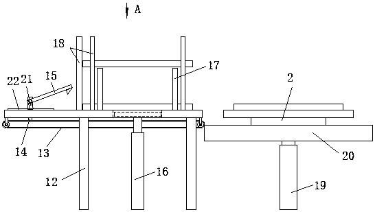
[0036] Embodiment 2: In this embodiment, three driving mechanisms and split bag clamping devices are provided respectively, and the driving mechanism is a ball screw transmission mechanism, which can convert rotation into linear movement, and has the function of reciprocating linear movement , is the prior art, and will not be repeated here. Crossbeams are arranged between the upper two corners of the two rectangular plates, and the ball screw transmission mechanism is fixedly connected to the crossbeams of the first bracket 1 in parallel with each other, and the moving direction of the ball slider is consistent with the direction of the drag bag. The disassembled bag clamping devices are respectively fixedly connected to the ball sliders of the corresponding ball screw transmission mechanism, so as to realize the linear reciprocating movement in the direction of dragging the bag.

[0037] Among them, the position of the ball screw transmission mechanism in the middle is fixed...


PUM


Abstract

The invention relates to an unstacker. The unstacker comprises a first support, a supporting plate located on one side of the first support, and a second lifting mechanism for driving the supporting plate to vertically move. A demounting and bag clamping device located on one side above the supporting plate is arranged on the first support, and the demounting and bag clamping device comprises a clamp matched with material bags. A driving mechanism for driving the demounting and bag clamping device to do reciprocating motion in the bag dragging direction is further included. According to the unstacker, a traditional manual unstacking mode is changed, reciprocating motion is done according to the path set by a user procedure, the moving stroke is not increased along with lowering of a stack,energy consumption is reduced, and the stacking time is saved; the unstacking efficiency is improved, the unstacking labor force is freed up, and a large amount of time is saved; and unstacked emptytrays can be automatically collected and stacked in one row, potential danger occurring when workers recycle the trays is avoided, and the safety of the workers is improved.

Description

technical field [0001] The invention relates to the field of unstacking equipment, in particular to an unstacking machine. Background technique [0002] In production, in order to facilitate the transportation of material bags, the material bags are usually stacked on the pallet with a palletizer, which is convenient for transshipment with a forklift. When in use, the stacked material bags need to be de-stacked. In the traditional manual method, the working process is to use manual handling to grab, and then put it on the conveying equipment. Due to personnel management and increased output, the workload and labor intensity increase, and the efficiency of unstacking is low, which is inconvenient in actual production. Contents of the invention [0003] Aiming at the deficiencies in the prior art, the present invention provides a depalletizing machine, which changes the depalletizing mode, reduces energy consumption, and improves the depalletizing efficiency. [0004] The p...

Claims


Application Information

Patent Timeline
Patent Type & Authority Applications(China)
IPC IPC(8): B65G61/00B65G59/02
CPCB65G59/02B65G61/00B65G2201/0238
Inventor 胡玉洋
Owner 山东腾阳智能装备有限公司
Why Eureka
Try Eureka