Image encoding method and device, image decoding method and device, electronic equipment and system

A technology of image coding and coding blocks, which is applied in image communication, electrical components, digital video signal modification, etc., and can solve the problem that the encoder cannot choose the most effective

Pending Publication Date: 2020-01-03
ZTE CORP
View PDF0 Cites 6 Cited by
  • Summary
  • Abstract
  • Description
  • Claims
  • Application Information

AI Technical Summary

Problems solved by technology

[0004] Embodiments of the present invention provide an image encoding and decoding method and device, electronic equipment and system, to at least solve th

Method used


Image

  • Image encoding method and device, image decoding method and device, electronic equipment and system
  • Image encoding method and device, image decoding method and device, electronic equipment and system
  • Image encoding method and device, image decoding method and device, electronic equipment and system

Examples


Embodiment 1

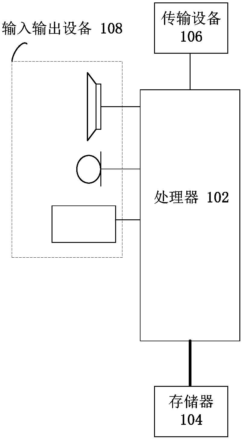
[0127] The method embodiment provided in Embodiment 1 of the present application may be executed in a mobile terminal, a computer terminal, or a similar computing device. Taking running on a mobile terminal as an example, figure 1 It is a hardware structural block diagram of a mobile terminal of an image coding method according to an embodiment of the present invention. Such as figure 1 As shown, the mobile terminal 10 may include one or more ( figure 1 Only one is shown in the figure) a processor 102 (the processor 102 may include but not limited to a processing device such as a microprocessor MCU or a programmable logic device FPGA) and a memory 104 for storing data. Optionally, the above-mentioned mobile terminal also A transmission device 106 for communication functions as well as input and output devices 108 may be included. Those of ordinary skill in the art can understand that, figure 1 The shown structure is only for illustration, and does not limit the structure o...

Embodiment 2

[0261] In this embodiment, a decoding method of an image running on the above-mentioned mobile terminal is provided, Figure 5 is a flow chart of decoding an image according to an embodiment of the present invention, such as Figure 5 As shown, the process includes the following steps:

[0262] Step S502, analyzing the code stream to determine the predicted value of the decoded block;

[0263] Step S504, parsing the code stream, and determining the scanning mode of the transform coefficients in the decoding block, the size of the coefficient group, and the value of syntax elements related to the transform coefficients;

[0264] Step S506: according to the scanning mode and the size of the coefficient group, process the coefficient group in the decoding block, and convert the syntax element into a transformation coefficient in the coefficient group;

[0265] Step S508, processing the transform coefficients to obtain restored values ​​of the transform coefficients;

[0266] S...

Embodiment 3

[0393] In this embodiment, an image encoding device is also provided, which is used to implement the above embodiments and preferred implementation modes, and those that have been described will not be repeated here. As used below, the term "module" may be a combination of software and / or hardware that realizes a predetermined function. Although the devices described in the following embodiments are preferably implemented in software, implementations in hardware, or a combination of software and hardware are also possible and contemplated.

[0394] Figure 8 is a structural block diagram of an image encoding device according to an embodiment of the present invention, such as Figure 8 As shown, the device includes: a first determination module 82 , a transformation module 84 , a second determination module 86 and an encoding module 88 .

[0395] The first determination module 82 is configured to determine the predicted value of the coding block, and calculate the prediction ...


PUM


Abstract

The invention provides an image encoding method and device, an image decoding method and device, electronic equipment and a system. The image encoding method comprises the following steps: determininga prediction value of a coding block, and calculating a prediction difference value between the coding block and the prediction value; carrying out one or more times of transformation on the prediction difference value to obtain transformation data, and determining a transformation coefficient by using the transformation data; determining a scanning mode of the transformation coefficients and thesizes of coefficient groups, dividing the transformation coefficients into one or more coefficient groups, scanning the transformation coefficients contained in each coefficient group according to the scanning mode, and converting the transformation coefficients into one or more syntax elements; and encoding the size of the coefficient group and the value of the syntax element, and writing encoded bits into a code stream. According to the image encoding method, the coding overhead of the coefficient group flag bit is effectively reduced, and the coding efficiency of the transformation coefficient is improved.

Description

technical field [0001] The present invention relates to the communication field, in particular, to an image encoding and decoding method and device, electronic equipment and system. Background technique [0002] The compression coding technology of digital video (Video) and image (Picture) uses the correlation between the sampling values ​​of pixels in the video and image to remove the redundancy existing in the video and image. Image compression uses the spatial domain correlation between adjacent pixel points (Pixel) samples (Sample) in the image, and reduces the distance between adjacent pixel points in the spatial domain by using adjacent encoded pixels to predict the pixel to be encoded. Redundancy between. This type of method is usually called intra prediction (IntraPrediction). Digital video consists of a series of consecutive images. In addition to using the correlation between adjacent pixels in the spatial domain of a single frame image, digital video compressio...

Claims


Application Information

Patent Timeline
IPC IPC(8): H04N19/176H04N19/503H04N19/593H04N19/18H04N19/147H04N19/124
CPCH04N19/176H04N19/503H04N19/593H04N19/18H04N19/124H04N19/147H04N19/129H04N19/119H04N19/157H04N19/70H04N19/117H04N19/159
Inventor 李明
Owner ZTE CORP
Why Eureka
Try Eureka