A self-adjusting speed bump with high safety performance

A safety performance, self-adjusting technology, applied to roads, buildings, road signs, etc., can solve the problems of speed bumps, speed reduction, etc., and achieve the effect of less bumpy feeling

Active Publication Date: 2021-08-24
梁山陆畅通专用车制造有限公司
View PDF0 Cites 0 Cited by
  • Summary
  • Abstract
  • Description
  • Claims
  • Application Information

AI Technical Summary

Problems solved by technology

[0005] The purpose of the present invention is to solve the problem that the above-mentioned deceleration belt is difficult to reduce the speed of the vehicle in actual use, and to provide a self-adjusting deceleration belt with good deceleration effect and high safety performance

Method used


Image

  • A self-adjusting speed bump with high safety performance
  • A self-adjusting speed bump with high safety performance
  • A self-adjusting speed bump with high safety performance

Examples


Embodiment 1

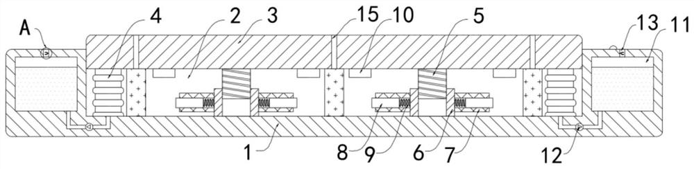
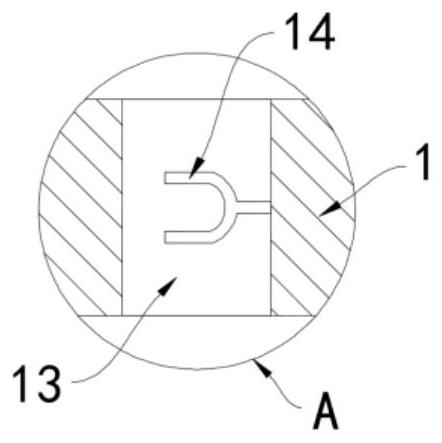
[0021] Such as Figure 1-2 As shown, a self-adjusting deceleration belt with high safety performance includes a base 1, a chute 2 is provided on the upper surface of the base 1, and a deceleration block 3 is slidably connected to the side wall of the chute 2. It should be noted that the deceleration block 3 is provided with a plurality of sound-absorbing holes 15 set through the deceleration block 3. The chute 2 communicates with the outside world through the silencing holes 15. The chute 2 is provided with silencing cotton at the position of the silencing holes 15, and the noise caused by the vehicle passing through the deceleration belt passes through. The sound-absorbing hole 15 enters the chute 2 and is absorbed by the sound-absorbing cotton, which plays a good effect of silencing and noise reduction. The deceleration block 3 is fixedly connected with the bottom surface of the chute 2 through the elastic air bag 4, wherein the elastic air bag 4 is made of rubber material b...

Embodiment 2

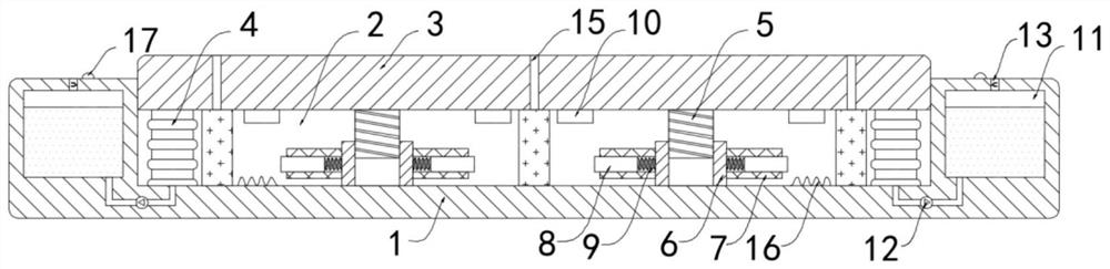
[0029] Such as image 3 As shown, the difference between this embodiment and Embodiment 1 is that a closed coil 16 is fixedly installed on the bottom surface of the chute 2, an LED lamp 17 is fixedly installed on the upper end of the base 1 at the water outlet 13, and the LED lamp 17 and the closed coil 16 form a closed loop.

[0030] In this embodiment, when the vehicle passes the deceleration belt, it drives the two permanent magnet blocks 8 to rotate. It can be known from the electromagnetic induction phenomenon that the conductor in the changing magnetic flux will generate an electromotive force, and then an induced current will be generated in the closed coil 16 to make the LED lamp 17 emits light, and the light that LED lamp 17 sends is irradiated on the atomized water, forming comparatively obvious light mist, has played good warning effect, reminds the driver to reduce the speed of a vehicle.


PUM


Abstract

The invention belongs to the field of municipal road facilities, and in particular relates to a self-adjusting speed bump with high safety performance, which includes a base, a chute is provided on the upper surface of the base, and a deceleration block is slidably connected to the side wall of the chute. The deceleration block is fixedly connected to the bottom surface of the chute through the elastic airbag, the lower surface of the deceleration block is fixedly connected with a plurality of lifting rods, and the bottom surface of the chute is rotatably connected with a plurality of sleeves, and the sleeves are sleeved Outside the lifting rod and threaded with the lifting rod, two rotating tubes are fixedly connected to the side wall of the sleeve, and a permanent magnet block is slidably connected inside the rotating tube, and the permanent magnet block is fixed to the sleeve by a return spring connected, the lower surface of the deceleration block is fixedly connected with a magnet ring. The invention can make the vehicles with slower speed pass safely and comfortably, and give the faster vehicles a more obvious bumpy feeling, thereby forcing the driver to slow down the speed, providing guarantee for safe driving on the road, and has a good warning effect.

Description

technical field [0001] The invention belongs to the field of municipal road facilities, in particular to a self-adjusting speed bump with high safety performance. Background technique [0002] Speed ​​bumps are generally set at road crossings, industrial and mining enterprises, schools, residential quarters, etc., where vehicles need to slow down and where traffic accidents are likely to occur. It is a new type of special traffic safety device for reducing the speed of motor vehicles and non-motor vehicles . [0003] When the vehicle passes through the speed reduction belt, the driver often actively slows down in order to avoid the large vibration of the vehicle, so as to achieve the effect of deceleration. However, in actual situations, when the vehicle passes through the speed reduction belt, even if the speed is slowed down, the speed reduction belt will still bring more obvious effects. With the improvement of the shock absorption performance of most vehicles, drivers o...

Claims


Application Information

Patent Timeline
Patent Type & Authority Patents(China)
IPC IPC(8): E01F9/529E01H3/04E01C17/00
CPCE01C17/00E01H3/04E01F9/529
Inventor 杨程聆胡建
Owner 梁山陆畅通专用车制造有限公司
Why Eureka
Try Eureka