Cutter deceleration method and device

A technology of cutter and deceleration movement, which is applied in the direction of printing device, printing, metal processing, etc. It can solve the problems of bumping into the printer, damage of the cutter, and bad printer body, and achieve the effect of avoiding collision

Active Publication Date: 2020-04-17
湖南鼎一致远科技发展有限公司
View PDF8 Cites 2 Cited by
  • Summary
  • Abstract
  • Description
  • Claims
  • Application Information

AI Technical Summary

Problems solved by technology

[0002] In the paper cutting module of the printer, the cutter is easy to hit the side wall of the printer at a high

Method used


Image

  • Cutter deceleration method and device
  • Cutter deceleration method and device
  • Cutter deceleration method and device

Examples


Embodiment Construction

[0035] The principles and features of the present invention are described below, and the examples given are only used to explain the present invention, and are not intended to limit the scope of the present invention.

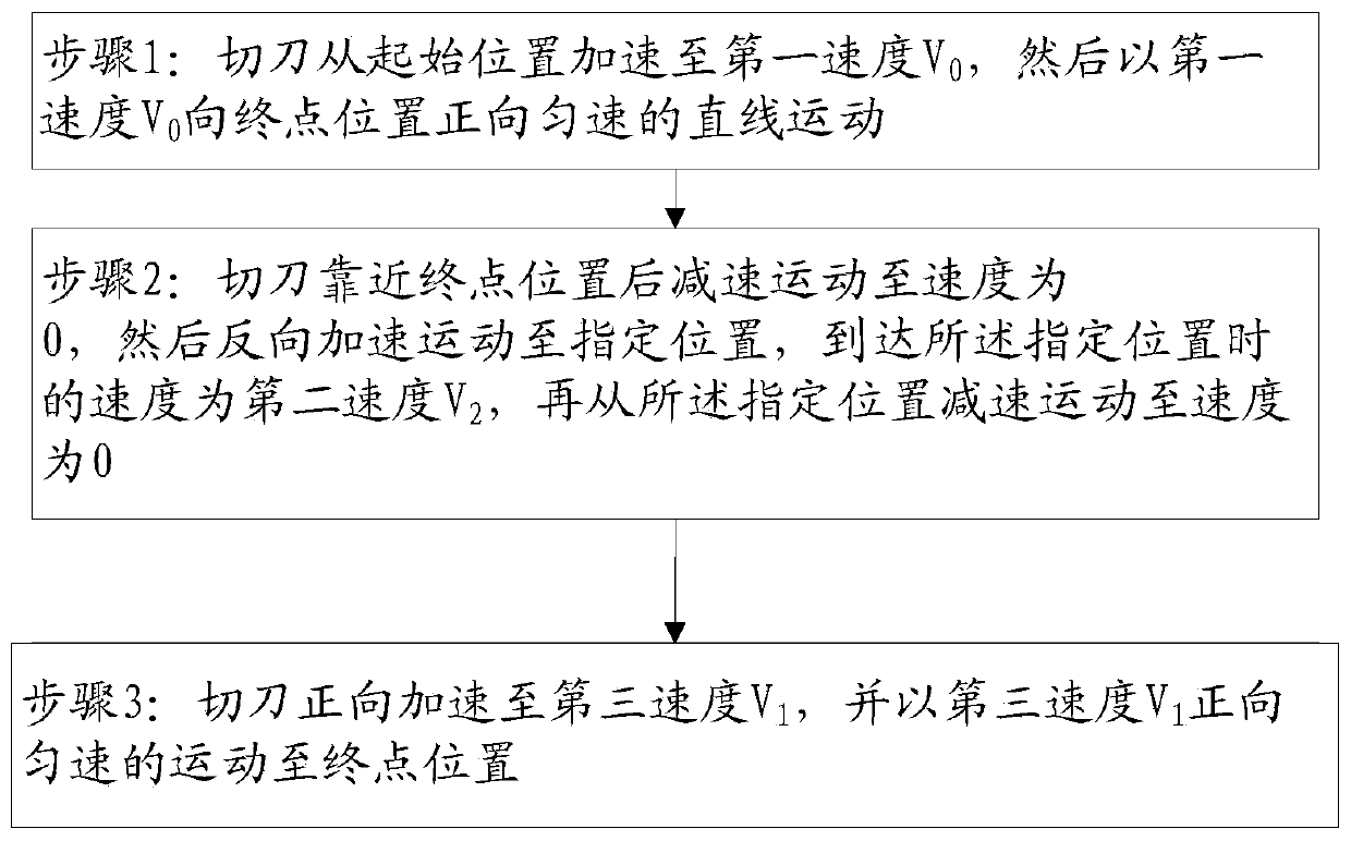
[0036] Such as Figure 1-Figure 2 As shown, the present embodiment provides a cutter deceleration method, including:

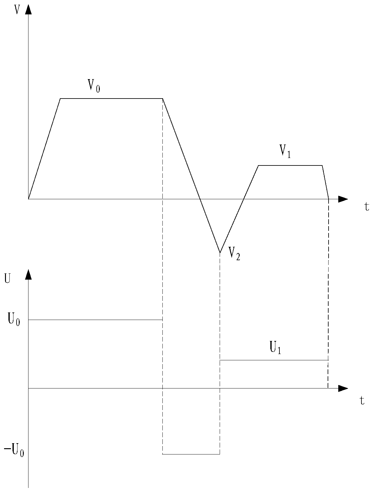
[0037] Step 1: The cutter accelerates from the starting position to the first speed V 0 , and then at the first velocity V 0 Straight line motion at a constant speed towards the end position;

[0038] Step 2: After the cutter approaches the end position, it decelerates to a speed of 0, then accelerates in the opposite direction to a designated position, and the speed when it reaches the designated position is the second speed V 2 , and then decelerate from the specified position until the speed is 0.

[0039] As a further solution of this embodiment, V 2 0 .

[0040] As a further solution of this embodiment, step 3 is also included: the c...


PUM


Abstract

The invention relates to a cutter deceleration method and device, wherein the cutter deceleration method comprises the steps: step 1, a cutter is accelerated to a first speed V0 from an initial position, and the cutter linearly moves forwards to a final position at the first speed V0 at a constant speed; and step 2, after the cutter gets close to the final position, the cutter is decelerated to the speed of 0, then the cutter is reversely accelerated to a designated position, the speed when the cutter reaches the designated position is the second speed V2, and then the cutter is decelerated tothe speed of 0 from the designated position. The cutter deceleration method and device have the beneficial effects that the cutter is decelerated and moves reversely after getting close to the finalposition, the purpose of avoiding collision through braking is achieved, meanwhile, inertia of the cutter can be overcome through reverse driving, and the situation that the cutter collides forwards with the side wall of a printer at a high speed by means of inertia due to immediate braking can be avoided.

Description

technical field [0001] The invention relates to the field of printers, in particular to a cutting knife deceleration method and device. Background technique [0002] In the paper cutting module of the printer, the cutter is easy to hit the side wall of the printer at a high speed after cutting the paper, which will cause damage to the cutter and is not good for the main body of the printer. [0003] Therefore, those skilled in the art urgently need a cutter deceleration method and device. Contents of the invention [0004] The technical problem to be solved by the invention is to prevent the cutter from colliding with the side wall of the printer at high speed after cutting paper. [0005] The technical solution of the present invention to solve the above-mentioned technical problems is as follows: a cutting knife deceleration method, comprising: [0006] Step 1: The cutter accelerates from the starting position to the first speed V 0 , and then at the first velocity V ...

Claims


Application Information

Patent Timeline
IPC IPC(8): B26D5/00B26D7/22B41J11/70
CPCB26D5/005B26D7/22B26D2005/002B41J11/70
Inventor 李留祥唐国初
Owner 湖南鼎一致远科技发展有限公司
Why Eureka
Try Eureka