
Light mechanical arm type massager
A technology of a mechanical arm and a massager, which is applied to kneading massage appliances, vibration massage, mechanical equipment, etc., can solve the problems of inconvenient use and large size of the massager, and achieve convenient operation, simple structure, and relief of numbness Effect
- Summary
- Abstract
- Description
- Claims
- Application Information
AI Technical Summary
Problems solved by technology
Method used
Image

Examples
Embodiment Construction
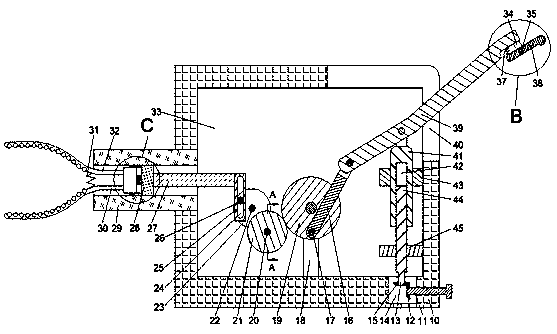
[0015] Combine below Figure 1-4 The present invention is described in detail, wherein, for the convenience of description, the orientations mentioned below are defined as follows: figure 1 The up, down, left, right, front and back directions of the projection relationship itself are the same.
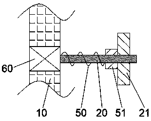
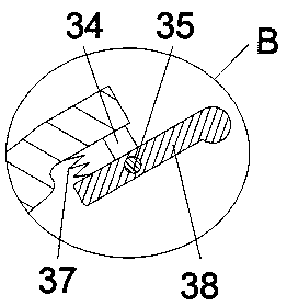
[0016] combined with Figure 1-4 The massager of a light-duty mechanical arm type includes a body 10, a cavity 33 is arranged in the body 10, a kneading mechanism 72 is arranged in the inner wall on the left side of the cavity 33, and a kneading mechanism 72 is arranged on the left side of the cavity 33. A lifting mechanism 70 is fixed on the side inner wall, a hammering mechanism 71 is arranged above the lifting mechanism 70, a motor 60 is fixed inside the rear inner wall of the cavity 33, and a spline extending forward is connected to the motor 60 for power. shaft 20, the spline shaft 20 is splined with a pinion 51, and the right end surface of the pinion 51 is fixedly provided wit...
PUM
 Abstract
Description
Claims
Application Information