
a clothing model
A technology of clothing models and mannequins, applied in the direction of shafts and bearings, dummy, pivots, etc., can solve the problems that the joints of clothing models cannot achieve effective rotation and effective fixation
- Summary
- Abstract
- Description
- Claims
- Application Information
AI Technical Summary
Problems solved by technology
Method used
Image

Examples
Embodiment Construction
[0021] The present invention will be further described in conjunction with the accompanying drawings and specific embodiments.
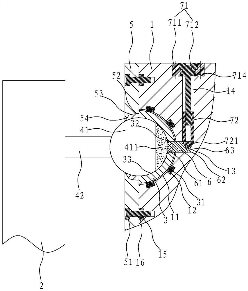
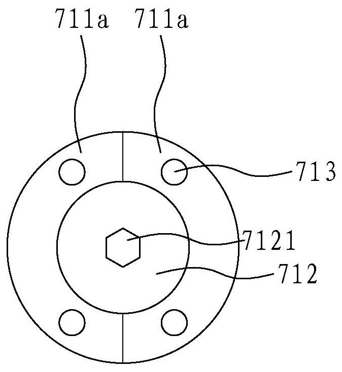
[0022] refer to Figure 1 to Figure 4 , the present embodiment provides a clothing model, including a model body 1, a connecting piece 2 connected to the model body 1 through joints, a housing groove 11 is provided on the side of the model body 1, and a housing groove 11 is provided in the housing groove 11 There is a lubricating pad 3, and the lubricating pad 3 is a self-lubricating engineering plastic, and the accommodating groove 11 is provided with a clamping groove 12, and a spring 31 for pushing the lubricating pad 3 is arranged in the clamping groove 12, so that There is a gap between the accommodating groove 11 and the lubricating pad 3 .
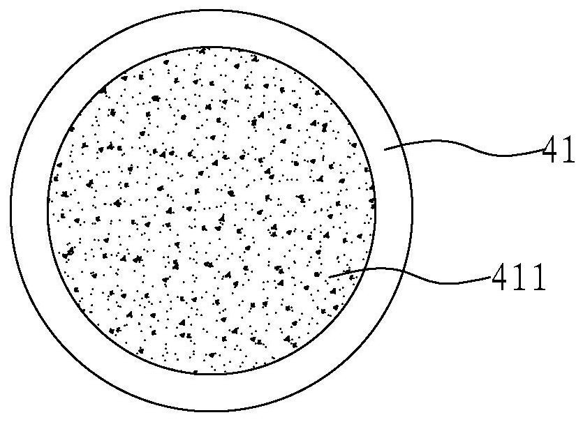
[0023] Described joint comprises spherical body 41, the connecting rod 42 that is arranged on spherical body 41, and described connector 2 is arranged on connecting rod 42, and connector 2 here can be arm...
PUM
 Abstract
Description
Claims
Application Information