Cleaning and draining system for mechanical part machining

A technology for mechanical parts and draining, which is applied in the field of cleaning and drying equipment for the processing of automotive mechanical parts, can solve the problems of low work efficiency, general cleaning effect, and heavy drying process workload, and achieves good use effect and structural design. precise effect

Active Publication Date: 2020-07-24
湖北冶鑫汽车零部件有限公司
View PDF6 Cites 7 Cited by
  • Summary
  • Abstract
  • Description
  • Claims
  • Application Information

AI Technical Summary

Problems solved by technology

The existing relatively common method is to put a large number of such parts into the cleaning tank for cleaning, and then take them away and dry them. However, due to the accumulation of parts during cleaning, the cleaning effect of this method is average, and the subsequent The drying process has a large workload and low work efficiency

Method used


Image

  • Cleaning and draining system for mechanical part machining
  • Cleaning and draining system for mechanical part machining
  • Cleaning and draining system for mechanical part machining

Examples


Embodiment 1

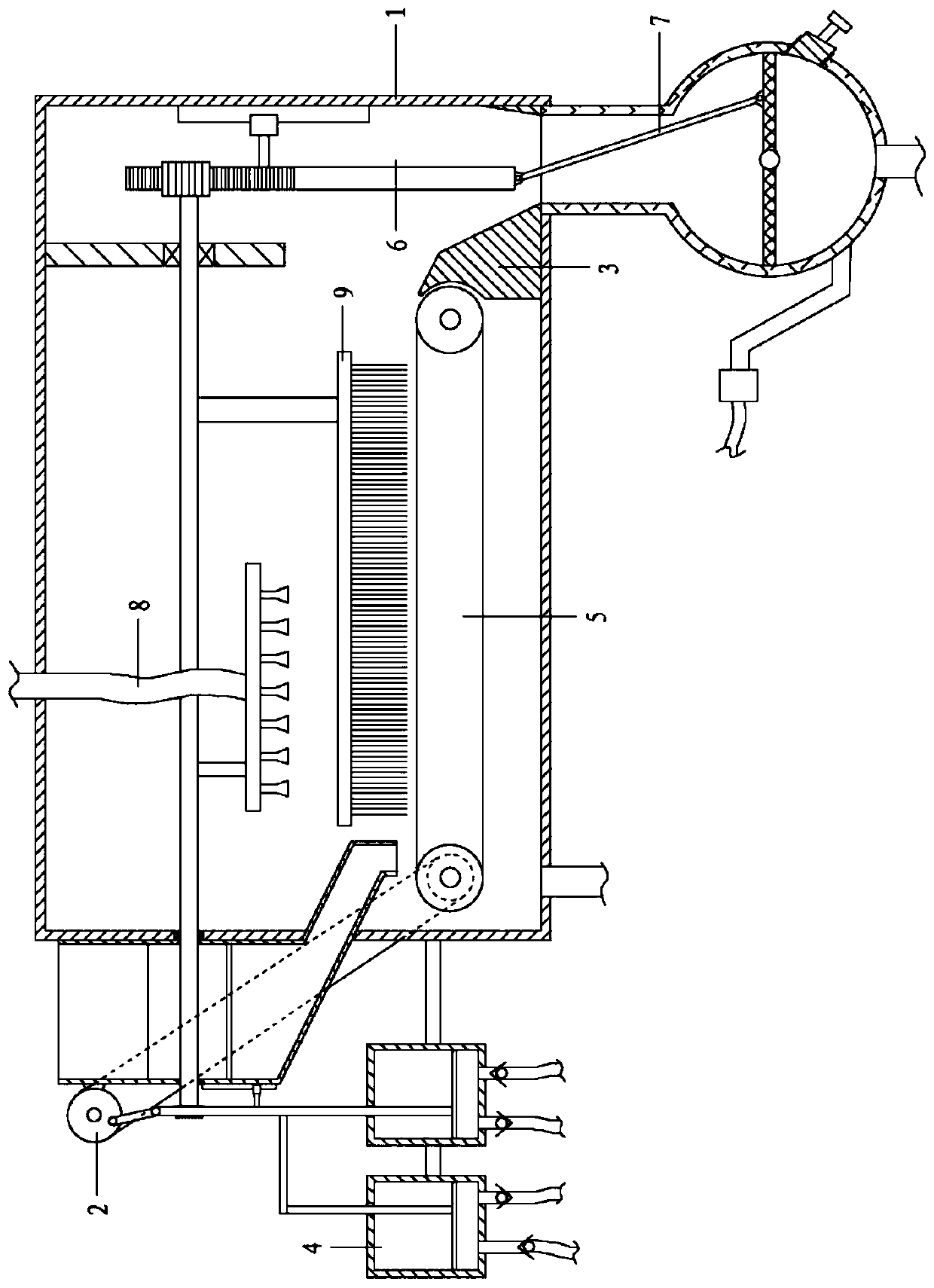
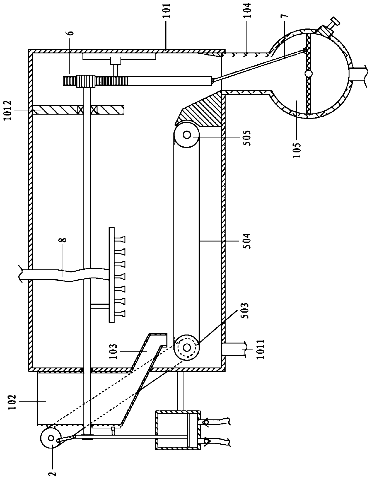
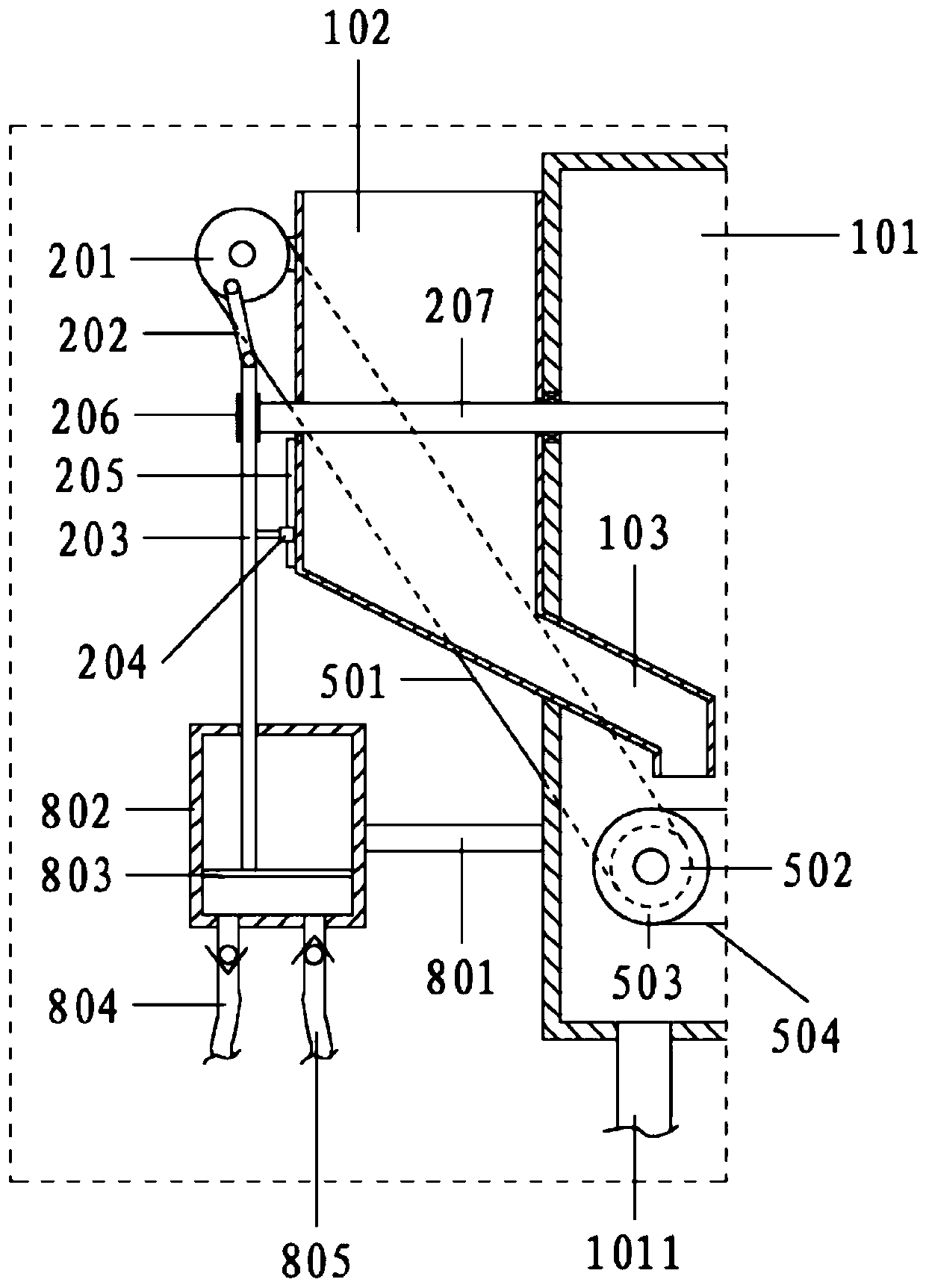
[0064] With reference to the accompanying drawings, a cleaning and draining system for processing mechanical parts includes a cavity assembly 1, a reciprocating assembly 2, a conveying assembly 5, a reciprocating assembly 6, a draining assembly 7, and a spray assembly 8;

[0065] The chamber assembly 1 includes a cleaning chamber 101, a feeding hopper 102, a feeding pipe 103, a feeding pipe 104 and a draining chamber 105; the feeding hopper 102 is fixed on the left side of the cleaning chamber 101, and the bottom end is connected with a feeding pipe 103; The material guide pipe 103 extends obliquely into the cleaning chamber 101, and the bottom outlet faces the left end of the conveying assembly 5; the conveying assembly 5 is arranged at the bottom of the cleaning chamber 101, and the right side of the conveying assembly 5 is provided with a baffle 3; There is a draining chamber 105 through the feeding pipe 104; a No. 1 reciprocating assembly 2 is arranged on the left side of t...

Embodiment 2

[0067] With reference to the accompanying drawings, a cleaning and draining system for processing mechanical parts includes a cavity assembly 1, a reciprocating assembly 2, a conveying assembly 5, a reciprocating assembly 6, a draining assembly 7, and a spray assembly 8;

[0068] The chamber assembly 1 includes a cleaning chamber 101, a feeding hopper 102, a feeding pipe 103, a feeding pipe 104 and a draining chamber 105; the feeding hopper 102 is fixed on the left side of the cleaning chamber 101, and the bottom end is connected with a feeding pipe 103; The material guide pipe 103 extends obliquely into the cleaning chamber 101, and the bottom outlet faces the left end of the conveying assembly 5; the conveying assembly 5 is arranged at the bottom of the cleaning chamber 101, and the right side of the conveying assembly 5 is provided with a baffle 3; There is a draining chamber 105 through the feeding pipe 104; a No. 1 reciprocating assembly 2 is arranged on the left side of t...

Embodiment 3

[0090] On the basis of the above examples,

[0091] It also includes a cleaning component 9; the cleaning component 9 is arranged in the cleaning chamber, including the third connecting rod 901, the mounting seat 902 and the bristles 903;

[0092] The mounting base 902 is arranged above the conveyor belt 504, and the top is connected with the main shaft 207 through the third connecting rod 901; the bottom surface of the mounting base 902 is equipped with bristles 903.

[0093] Specifically, the main shaft 207 is also swayed synchronously with the mounting base 902 , and the mechanical parts are scrubbed through the bristles 903 in cooperation with spraying, so as to optimize the cleaning effect on the mechanical parts.


PUM


Abstract

The invention relates to the field of cleaning and drying devices for automobile machine part machining, in particular to a cleaning and draining system for mechanical part machining. The cleaning anddraining system for mechanical part machining achieves integrated operation of conveying a mechanical part, conducting sprinkling and cleaning and conducting shaking and draining and is accurate in structural design and good in use effect. A servo motor is adopted to drive a first transmission wheel to rotate; on one hand, the first transmission wheel drives a first roller to rotate through a transmission belt, so that a conveyer belt is made to move, and parts fallen from a feeding hopper are moved rightwards; and on the other side, the first transmission wheel drives a first rack to move upand down through a first reciprocating rod, a first piston plate is made to synchronously move, through cooperation of a check valve, pumping discharge of cleaning liquid is achieved, and sprinklingand cleaning are conducted on the parts on the conveyer belt. A shaft also synchronously drives a second driven gear to swing, a second rack moves up and down under guide of a slider sliding rail, a draining mesh plate is driven to shake through a second reciprocating rod, the parts fallen onto the draining mesh plate move back and forth, and draining is accelerated.

Description

technical field [0001] The invention relates to the field of cleaning and drying equipment for processing automobile mechanical parts, in particular to a cleaning and drying system for processing mechanical parts. Background technique [0002] Vehicle is the general term for "vehicle" and the unit "vehicle" of the vehicle. The so-called car refers to a means of transportation on land that turns on wheels; the so-called car comes from the ancient method of measuring cars. Cars at that time generally had two wheels, so a car was called one or two when it was taken, and it was written as a car later. It can be seen that the original meaning of a vehicle refers to a vehicle that has no power itself. It is called a carriage when it is drawn by horses, and it is called a rickshaw when it is pulled or pushed by people. With the development of science and technology, there are automobiles towed by steam engines and so on. At this time, the concept of vehicles has quietly changed,...

Claims


Application Information

Patent Timeline
Patent Type & Authority Applications(China)
IPC IPC(8): B08B3/02B08B1/00B08B1/02B08B13/00F26B5/00F26B25/02F26B25/18
CPCB08B1/002B08B1/02B08B3/022B08B13/00B08B2203/0247B08B2203/0258F26B5/00F26B25/02F26B25/185
Inventor 徐丰詹习生杨青胜万里光涂建
Owner 湖北冶鑫汽车零部件有限公司
Why Eureka
Try Eureka