Power distribution cabinet

A technology for power distribution cabinets and cabinets, which is applied in the direction of electrical components, pull-out switch cabinets, switchgear, etc.

Pending Publication Date: 2020-07-28
天津市中力神盾电子科技有限公司
View PDF0 Cites 3 Cited by
  • Summary
  • Abstract
  • Description
  • Claims
  • Application Information

AI Technical Summary

Problems solved by technology

[0003] The purpose of the present invention is to overcome the defects in the prior art and provide a power distribution cabinet. The power distribution cabinet has a simple structure, is convenient for standardized production, and is convenient for installation and maintenance. The switch unit, monitoring terminal, and collection terminal can all realize Modular production, and the connection between them is fast, accurate and stable, without the complicated and messy wiring of strong and weak currents inside the traditional power distribution cabinet, and the problems that are prone to errors during assembly, which can significantly improve the production efficiency of the power distribution cabinet, and at the same time, it is not necessary to cut off the switch unit. It can also realize the di...

Method used


Image

  • Power distribution cabinet
  • Power distribution cabinet
  • Power distribution cabinet

Examples


Embodiment Construction

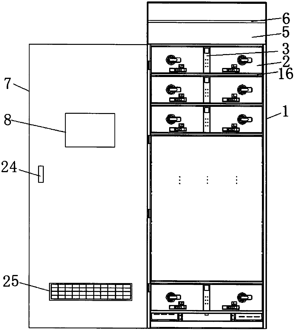
[0056] The power distribution cabinet of the present invention will be described in detail below with reference to the accompanying drawings.

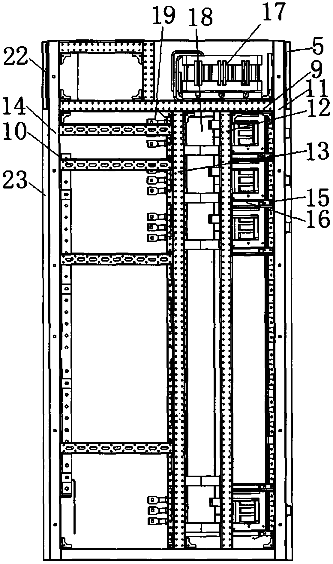
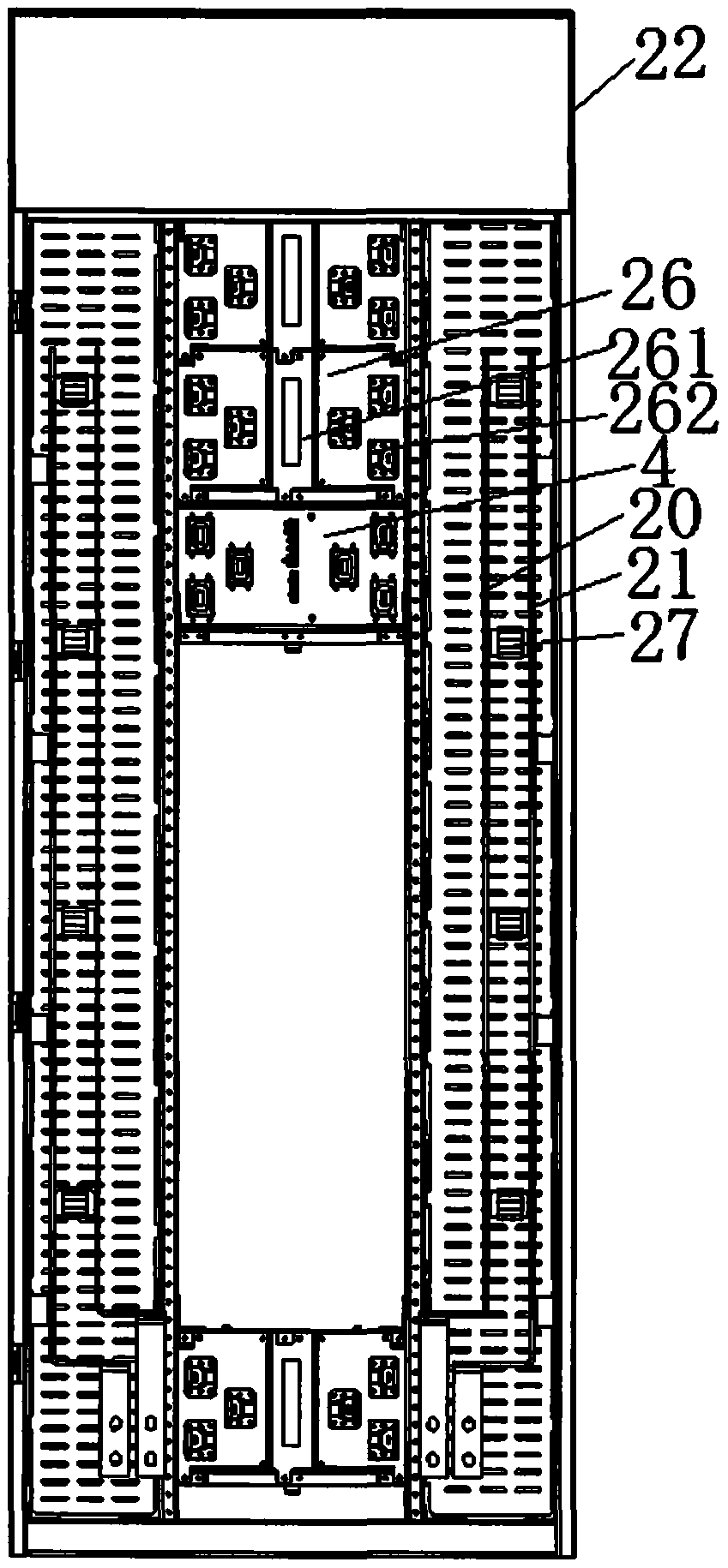
[0057] figure 1 It shows a schematic front view of the open state of the power distribution cabinet provided by the embodiment of the present invention; figure 2 It shows a schematic side view of the power distribution cabinet provided by the embodiment of the present invention; image 3 It shows a schematic rear view of the power distribution cabinet provided by the embodiment of the present invention; Figure 4 It shows a schematic front view of the switch unit in the power distribution cabinet provided by the embodiment of the present invention; Figure 5 It shows a schematic top view of the switch unit in the power distribution cabinet provided by the embodiment of the present invention; Image 6 It shows a schematic bottom view of the switch unit in the power distribution cabinet provided by the embodiment of the present inven...


PUM


Abstract

The invention provides a power distribution cabinet, which is characterized in that a cabinet body is provided with at least one switch unit, a monitoring terminal and an acquisition terminal; the switch unit is provided with an inlet wire connector assembly, an outlet wire connector assembly and a first signal connector; the monitoring terminal is provided with a first signal connector assembly;the acquisition terminal is provided with a second signal connector and a second signal connector assembly; the switch unit is connected with the second signal connector of the acquisition terminal through the first signal connector in an inserted manner; and the monitoring terminal is connected with the second signal connector assembly of the acquisition terminal through the first signal connector assembly in an inserted manner. The power distribution cabinet is simple in structure and convenient for standardized production, the switch unit, the monitoring terminal and the acquisition terminal can realize modular production, the connection among the switch unit, the monitoring terminal and the acquisition terminal is quick, accurate and stable, and the production efficiency is high. Meanwhile, the switch unit is simple in structure and convenient for miniaturized production. The power distribution cabinet can be provided with multiple columns of switch units at the same time, user requirements are met, the cost is reduced, local or remote monitoring, management, protection and control functions are achieved, and the working efficiency and the intelligent degree of the power distribution cabinet are improved.

Description

technical field [0001] The invention belongs to the technical field of high and low voltage power distribution equipment, and in particular relates to a power distribution cabinet. Background technique [0002] In the traditional power distribution cabinet, there are multiple withdrawable switch units inside the cabinet, and each switch unit is equipped with strong current equipment and weak current equipment. The manufacturing process is to move the components of the strong current equipment and weak current equipment to the At the cabinet body, each component is individually fixed in the corresponding drawer, and then the corresponding components are connected through the connecting wire, and finally the switch units of each drawer are set in the power distribution cabinet. The power distribution cabinet with this structure has the problems of complex assembly and slow production speed, which is not convenient for mass production and standardized production; moreover, the ...

Claims


Application Information

Patent Timeline
IPC IPC(8): H02B11/133H02B11/10H02B11/02
CPCH02B11/02H02B11/10H02B11/133
Inventor 孙巍巍
Owner 天津市中力神盾电子科技有限公司
Why Eureka
Try Eureka