A horizontal band sawing machine with an automatic feeding device

A technology of automatic feeding and band sawing machine, which is applied in the field of machine tools, can solve the problems of increased scrap rate, interrupted saw blade, difficult automatic feeding, etc., and achieves the effect of improving conveying stability, ensuring feeding stability, and avoiding free movement

Active Publication Date: 2020-11-17
中电建成都铁塔有限公司
View PDF3 Cites 0 Cited by
  • Summary
  • Abstract
  • Description
  • Claims
  • Application Information

AI Technical Summary

Problems solved by technology

Most of the feeding devices currently used are manually fed and then clamped with a vise. This scheme has good adaptability in terms of versatility, but its connection stability is poor. Therefore, currently on the market There are also some semi-automatic technical solutions, such as the patents whose authorized announcement numbers are CN208592458U, CN208592457U, and CN208513764U, respectively disclosing some automatic feeding solutions suitable for band sawing machines. The above-mentioned solutions can solve the problem of manual feeding to a certain extent. But it still has the problem of unbalanced precision and speed, and it is difficult to feed automatically. At the same time, the control of the feeding angle relies on magnetic links, and the power of the band sawing machine is strong, which can easily cause the workpiece to move, resulting in an increase in the scrap rate. , bring economic loss, or even break the saw blade, causing danger

Method used


Image

  • A horizontal band sawing machine with an automatic feeding device
  • A horizontal band sawing machine with an automatic feeding device
  • A horizontal band sawing machine with an automatic feeding device

Examples


Embodiment Construction

[0039] The present invention will be further described below in conjunction with the accompanying drawings and embodiments.

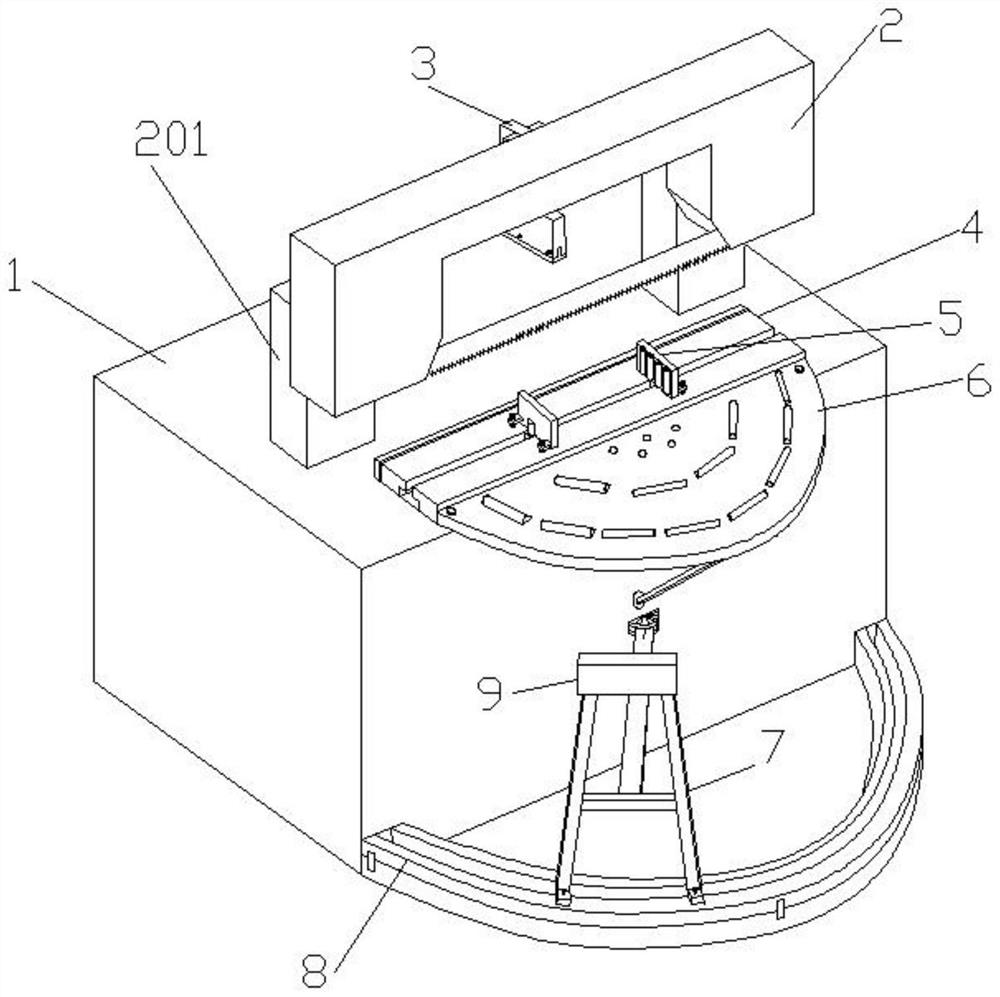
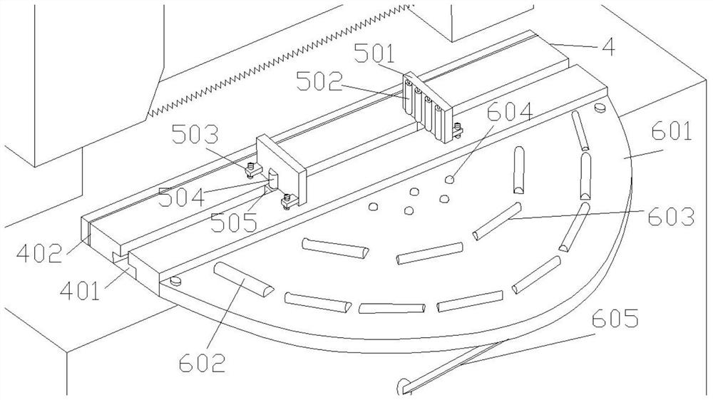
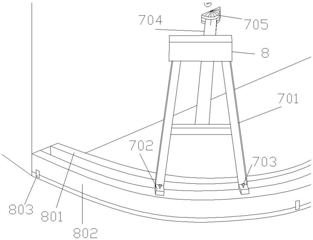
[0040] Such as Figure 1-3As shown, a horizontal band sawing machine with an automatic feeding device includes a band sawing machine base 1, a saw frame elevating device 201 is arranged on the band sawing machine base 1, a saw frame 2 is installed on the top of the saw frame 2, and in front of the saw frame 2 A workbench 4 is provided, and the position of the workbench 4 corresponding to the saw blade on the saw frame 2 is provided with a saw kerf 402. The front of the workbench 4 is provided with a semicircular conveying plate 6, and its straight edge section is close to the straight edge of the workbench 4, and the semicircle The end extends out of the band sawing machine base 1, and the bottom is provided with a support rod 605, and the support rod 605 is connected to the front side of the band sawing machine base 1 to support the semicircular convey...


PUM


Abstract

The invention discloses a horizontal band sawing machine with an automatic feeding device, which comprises a band sawing machine base, a saw frame lifting device is arranged on the band sawing machine base, a saw frame is installed on the top of the saw frame, and a working table is arranged in front of the saw frame , the position of the workbench corresponding to the saw blade on the saw frame is provided with a saw kerf, and a conveying plate is provided in front of the workbench. The conveying plate is provided with a conveying element and a motor. The motor can drive the conveying original to rotate, and the workpiece placed on the conveying element Conveying to the workbench; there is a movable support in front of the conveying plate, and a conveying plate is also set on the movable support. The conveying plate is also equipped with a conveying original and a motor, and the workpiece placed on the conveying element is conveyed to the workbench. The invention improves the clamping part and the conveying part so that it can meet better positioning accuracy and conveying efficiency, and at the same time meet the processing requirements of bar-shaped workpieces with different angles and shapes.

Description

technical field [0001] The invention relates to the technical field of machine tools, in particular to a horizontal sawing machine, in particular to a horizontal band sawing machine with an automatic feeding device. Background technique [0002] In the process of cutting strip-shaped materials, it is often necessary to use a horizontal sawing machine for cutting. The basic working principle of the horizontal sawing machine is: the saw bow with the saw blade reciprocates, and the saw frame is fed by swinging around the fulcrum. In the production process, when using a horizontal sawing machine to process long materials, the current common method is that workers need to place the materials on the bed, except for the parts that have been placed on the sawing machine, most of the materials are suspended. The suspended end is supported by a support frame to realize fixation. Most of the feeding devices currently used are manually fed and then clamped with a vise. This scheme has ...

Claims


Application Information

Patent Timeline
Patent Type & Authority Patents(China)
IPC IPC(8): B23D55/04B23D55/00
CPCB23D55/00B23D55/04B23D55/046
Inventor 付强叶德生邓富全管欢
Owner 中电建成都铁塔有限公司
Why Eureka
Try Eureka