Fan with impeller fairing structure

A technology of shroud and impeller, which is applied to parts of pumping devices for elastic fluids, mechanical equipment, machines/engines, etc., to achieve the effect of improving the distribution of intake air

Pending Publication Date: 2020-08-11
GUANGZHOU LUOSEN VENTILATION
View PDF0 Cites 0 Cited by
  • Summary
  • Abstract
  • Description
  • Claims
  • Application Information

AI Technical Summary

Problems solved by technology

[0003] Aiming at the deficiencies of the prior art, the technical problem solved by the present invention is how to improve the air intake distribution of the fan impeller, reduce turbulent flow, reduce noise and improve the air outlet efficiency of the fan at the same time

Method used


Image

  • Fan with impeller fairing structure

Examples


Embodiment Construction

[0010] The specific embodiments of the present invention will be further described below in conjunction with the accompanying drawings, but it is not a limitation of the present invention.

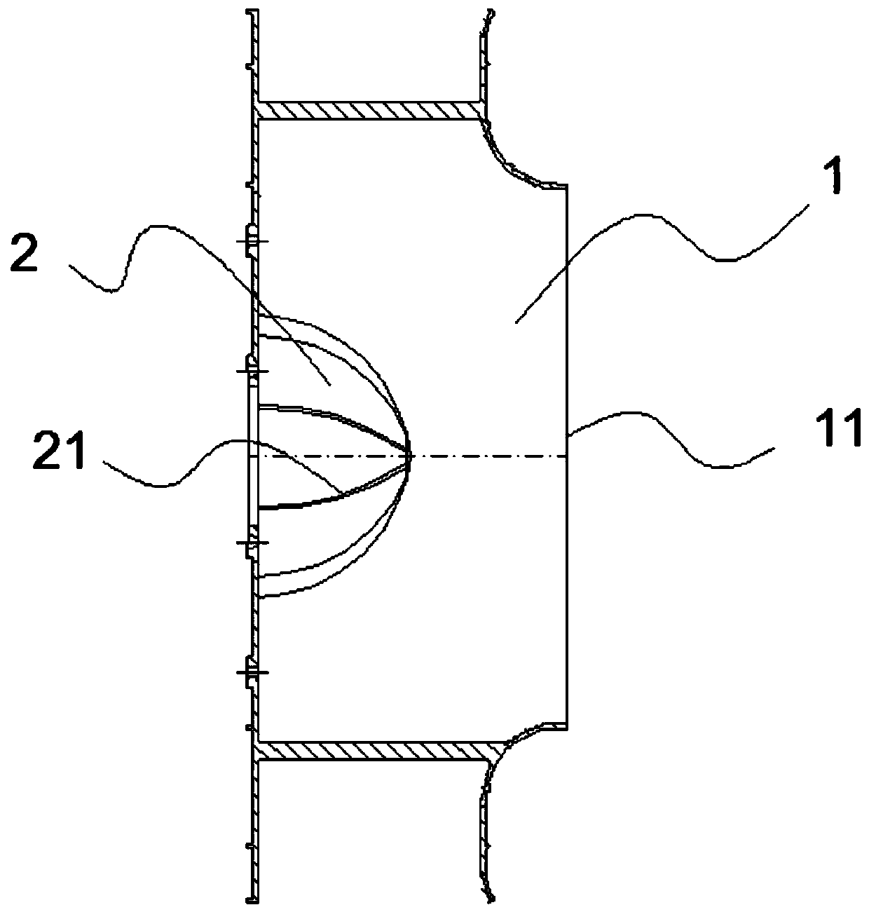
[0011] figure 1 Shows a fan with an impeller shroud structure, including an impeller body 1 and a finned shroud 2. The finned shroud 2 is hemispherically fixed on the inner surface of the impeller body 1 away from the air inlet 11 And with the air inlet 11 as the center, the outer surface of the fin-type deflector 2 is evenly provided with fins 21 that open outwards. The external airflow enters from the air inlet 11 and then divides by the fins 21 on the fin-type deflector 2. After that, the purpose of uniformly guiding the airflow to each part of the impeller body 1 is achieved.

[0012] The fins 21 are vertical fins, which are distributed evenly from the top center of the fin-type deflector 2 as the starting point to the bottom.

[0013] The fins 21 are spiral fins, which are distributed spir...


PUM


Abstract

The invention discloses a fan with an impeller fairing structure. The fan comprises an impeller body and a fin type fairing. The fin type fairing is hemispherical and is fixed to the inner surface ofthe side, away from an air inlet, of the impeller body, and fins expanded outwards are evenly arranged on the outer surface of the fin type fairing around the air inlet; and after external air flow enters the air inlet and is distributed by the fins on the fin type fairing, the aim of evenly guiding the air flow to all parts of the impeller body is achieved. According to the fan, air input distribution in the impeller is effectively improved, turbulent flow is reduced, the air output efficiency of the fan is improved, and noise is lowered.

Description

Technical field [0001] The present invention relates to the technical field of fan component manufacturing, in particular to a fan with an impeller guide cover structure, including an impeller body and a guide cover. Background technique [0002] The working principle of the fan is to use the relative movement of the impeller in the fan housing to compress and transport the gas, pressurize and accelerate the air flow through the impeller, and convert electrical energy into the kinetic energy and potential energy of the gas. In the prior art, the work efficiency of the fan impeller is closely related to the air intake efficiency. The problem that has always plagued centrifugal fans is that the part of the impeller close to the air inlet has a lot of air intake, and the part far away from the air inlet has less air intake, resulting in uneven air flow. The formation of turbulent flow reduces the air outlet efficiency of the fan and also increases the noise of the fan. Summary of t...

Claims


Application Information

Patent Timeline
Patent Type & Authority Applications(China)
IPC IPC(8): F04D29/28F04D29/66F04D29/62
CPCF04D29/281F04D29/626F04D29/666F04D29/667
Inventor 高显孙仲华
Owner GUANGZHOU LUOSEN VENTILATION
Why Eureka
Try Eureka