Collector with air outlet flow guide structure

A technology of a collector and an air outlet is applied to the collector body and the shroud, and the field of the collector with the air outlet guide structure to achieve the effect of improving the distribution of the air intake.

Pending Publication Date: 2020-08-11
GUANGZHOU LUOSEN VENTILATION
View PDF0 Cites 0 Cited by
  • Summary
  • Abstract
  • Description
  • Claims
  • Application Information

AI Technical Summary

Problems solved by technology

[0003] Aiming at the deficiencies of the prior art, the technical problem solved by the present invention is how to improve the air intake distribution of the fan impeller, reduce turbulent flow, reduce noise and improve the air outlet efficiency of the fan at the same time

Method used


Image

  • Collector with air outlet flow guide structure
  • Collector with air outlet flow guide structure

Examples


Embodiment Construction

[0012] The specific embodiments of the present invention will be further described below in conjunction with the accompanying drawings, but the present invention is not limited.

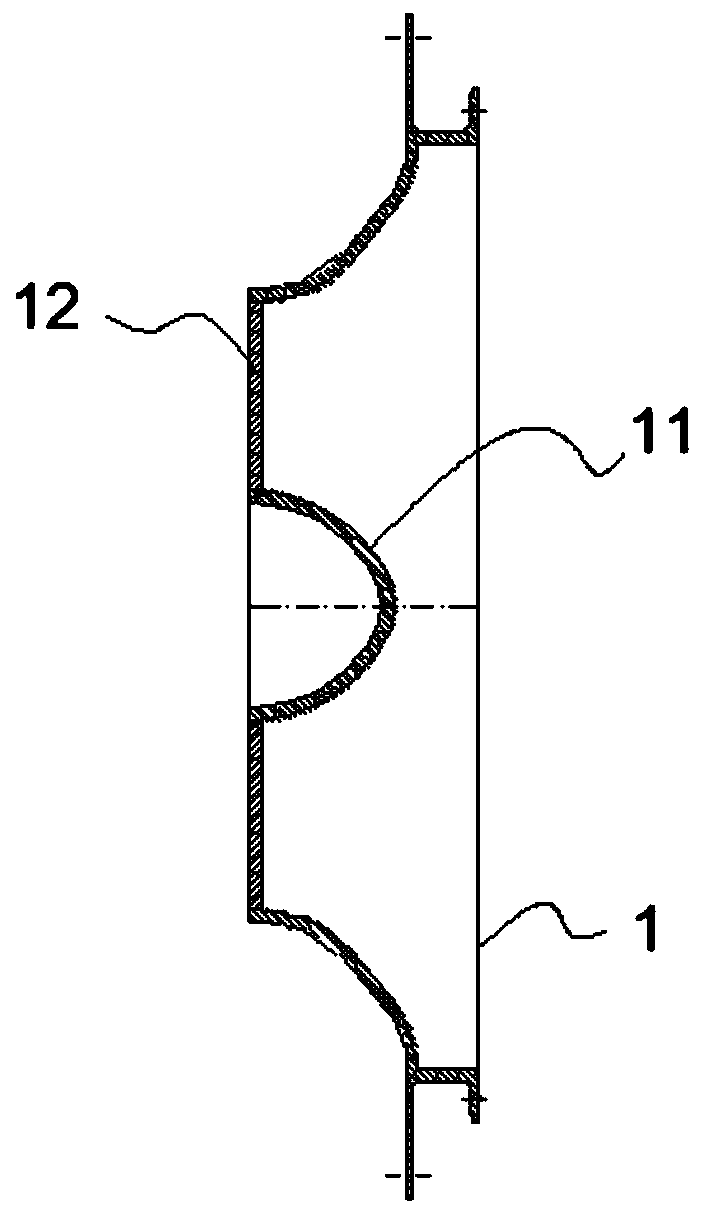
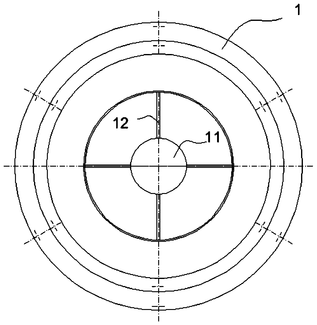
[0013] figure 1 , figure 2 Shown is a current collector with an air outlet guide structure, including a collector body 1 and a guide cover 11, the guide cover 11 is a shell, and a number of evenly distributed connecting ribs 12 are provided on the lower edge of the shell It is fixedly connected with the inner wall of the air outlet port of the collector body 1, and after the external incoming air flow is diverted along the casing of the shroud 11, the purpose of evenly diverting the air flow to the inner cavity of the impeller is realized.

[0014] The shroud 11 is a nearly hemispherical rotating shell.

[0015] In order to reduce the influence on the intake air flow, as an improvement of the present invention, the number of connecting ribs 12 is four.

[0016] The connecting rib 12 is fixedly co...


PUM


Abstract

The invention discloses a collector with an air outlet flow guide structure. The collector comprises a collector body and a flow guide cover, wherein the flow guide cover is a shell; a plurality of uniformly distributed connecting ribs are arranged on the lower edge of the shell and are fixedly connected with the inner wall of an air outlet port of the collector body; and after external air inflowis guided along the shell of the flow guide cover, the purpose of uniformly guiding the air flow into an inner cavity of an impeller is realized. According to the collector, the air inflow distribution of the inner cavity of the impeller is effectively improved, turbulent flow is reduced, the air outlet efficiency of a fan is improved, and noise is reduced.

Description

technical field [0001] The invention relates to the technical field of fan component manufacturing, in particular to a collector with an air outlet guide structure, including a collector body and a guide cover. Background technique [0002] The working principle of the fan is to use the relative movement of the impeller in the fan housing to compress and transport the gas, pressurize and accelerate the air flow through the impeller, and convert the electrical energy into the kinetic energy and potential energy of the gas. In the prior art, the working efficiency of the fan impeller is closely related to the air intake efficiency. The problem that has plagued centrifugal fans for a long time is that the part of the impeller close to the air inlet has more air intake, and the part far away from the air inlet has less air intake, resulting in uneven air flow and easy The formation of turbulent flow reduces the air outlet efficiency of the fan and increases the noise of the fan....

Claims


Application Information

Patent Timeline
IPC IPC(8): F04D29/44F04D29/66
CPCF04D29/441F04D29/667
Inventor 孙仲华高显
Owner GUANGZHOU LUOSEN VENTILATION
Why Eureka
Try Eureka