Desiccant cup with integral filter

a desiccant cup and filter technology, applied in the field of desiccant containers, can solve the problems of reducing system efficiency, affecting the efficiency of air conditioning systems, damage to compressors, etc., and achieve the effects of reducing noise, and reducing time and cos

Inactive Publication Date: 2005-11-29
HALLA CLIMATE CONTROL CANADA
View PDF43 Cites 6 Cited by
  • Summary
  • Abstract
  • Description
  • Claims
  • Application Information

AI Technical Summary

Benefits of technology

[0014]Advantageously, different embodiments of the present invention may permit: the elimination of noise created in the air conditioning system when polyester, polypropylene matted, other matted synthetic fibre, cotton fibre, low permeation or needled felt are used as filters; the reduction of cost by eliminating the need to purchase separate filters for the desiccant container; the reduction of time and cost relating to the labour required to install separate filters for the desiccant container; a desiccant container incorporating integral filtration with significant open area, thereby reducing pressure drop (as compared to a container with less open area); the provision of a filter for 100% of the liquid above the oil bleed hole of the accumulator, which provides a significant advantage since a typical oil bleed filter (located in or near the oil bleed aperture) is small in size and can become partially or completely blocked with a relatively small amount of contamination (thereby disrupting oil flow); and increasing the efficiency of the air conditioning system.

Problems solved by technology

Liquid refrigerant entering the compressor causes “flooding” which in turn reduces system efficiency and can damage the compressor.
Accumulators and receivers / dryers often incorporate a desiccant to prevent (or at least limit) moisture ingression in the compressor and the resulting damage or loss of efficiency to the air conditioning system.
Such bags are problematic because they can be easily damaged during assembly and / or testing.
A tear in the bag allows the loose desiccant particles to escape and potentially enter the air-conditioning system, where they can damage the accumulator and other components.
However, there are certain drawbacks associated with the use of such filter discs.
For example, the materials used within the filter discs, such as polyester or polypropylene matted or needles felt, for example, have been known to stimulate a reaction with the air conditioning refrigerant R-134A to create a significant noise within the air conditioning system.
However, such cups require additional filter layers placed against the cap and cup bottom.
One drawback is that diameter of the holes is large enough to allow desiccant particles to pass through or become caught or blocked in the holes.

Method used


Image

  • Desiccant cup with integral filter
  • Desiccant cup with integral filter
  • Desiccant cup with integral filter

Examples


Embodiment Construction

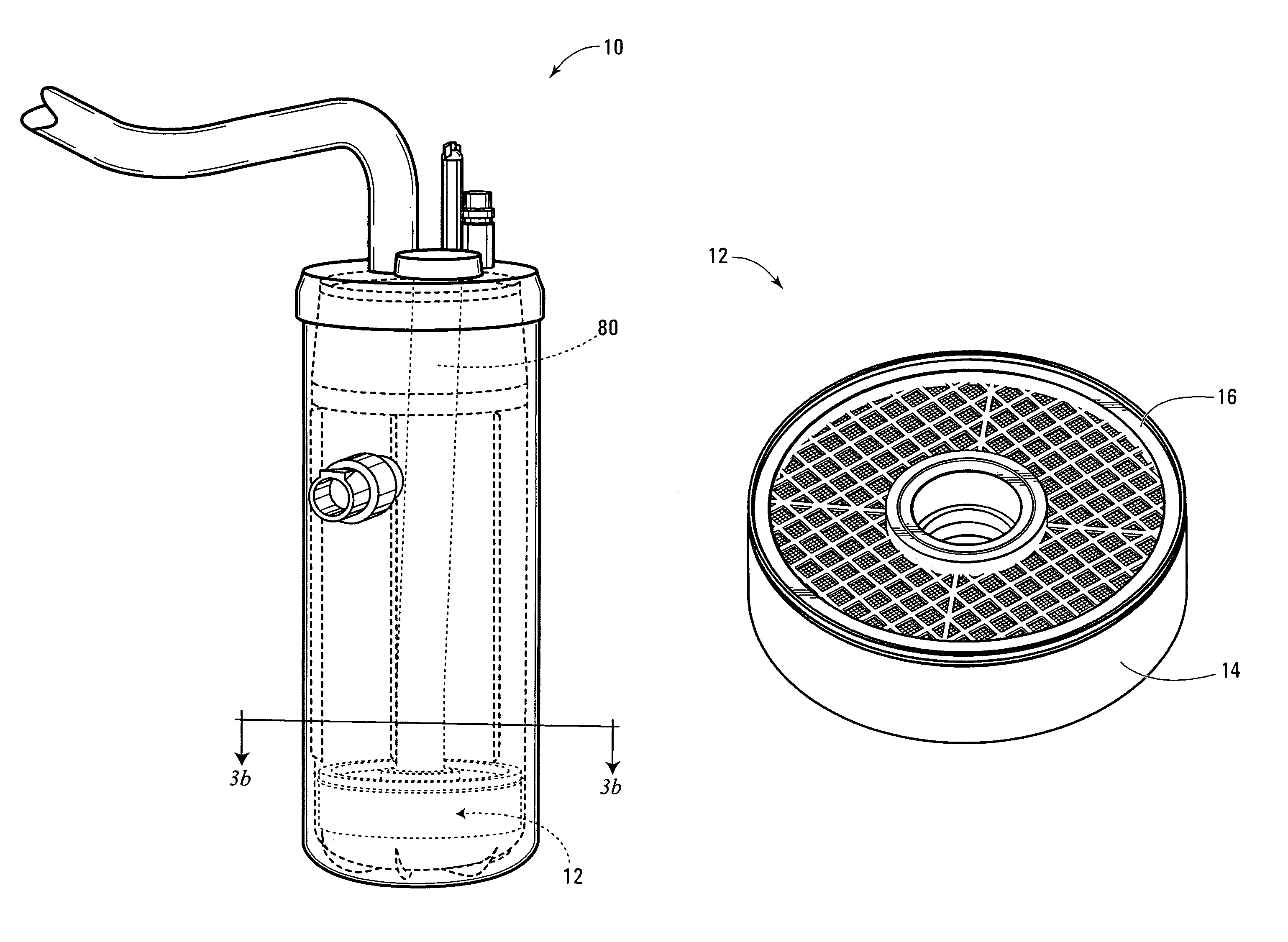
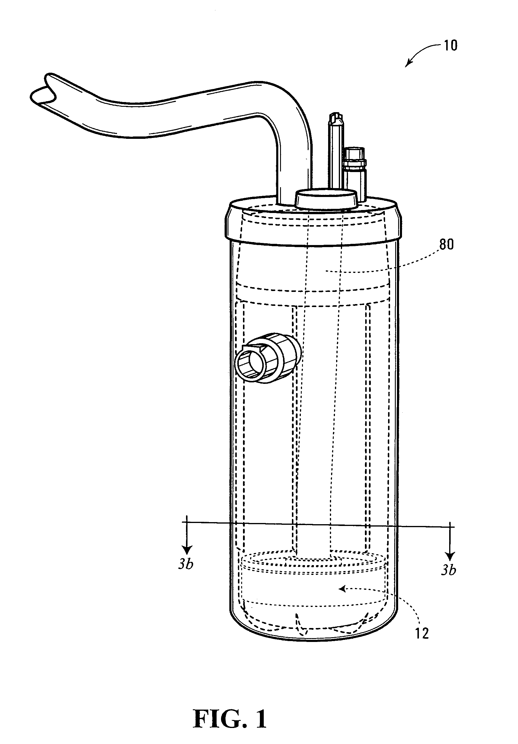
[0027]FIG. 1 shows a representative accumulator or refrigerant storage device 10 for an air conditioning (or heating, ventilation and air conditioning (HVAC)) system of a vehicle. The accumulator 10 as shown in FIG. 1 has certain features omitted for simplicity and certain features inside the accumulator 10 are shown by dotted outline. A desiccant container 12 according to an aspect of the present invention is shown roughly in position within the accumulator 12, for example purposes.

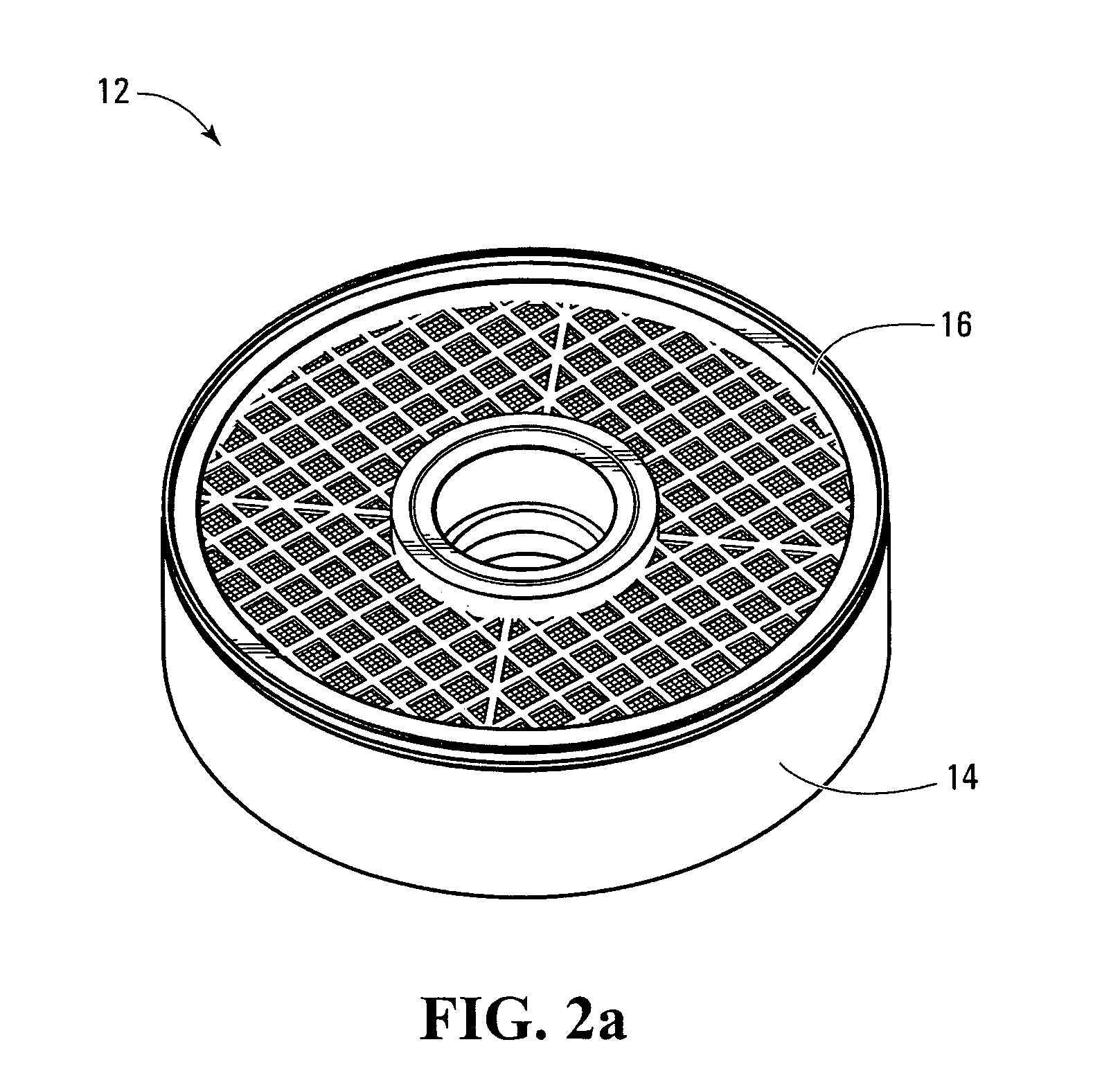
[0028]FIG. 2a is a perspective view of the desiccant container 12. The desiccant container 12 has two portions, namely an open body or cup portion 14 and a lid 16. FIG. 2b is a perspective view of the lid 16. FIG. 2d is a perspective view of the open cup 14.

[0029]As perhaps best seen in FIG. 2b, the lid 16 is a one-piece casting. The lid 16 is a generally circular, one-piece casting, having a generally circular outer or peripheral boundary 20 and a concentric, generally circular, inner boundary 22, formi...


PUM

PropertyMeasurementUnit
diameteraaaaaaaaaa
latticeaaaaaaaaaa
structureaaaaaaaaaa

Abstract

A desiccant container for use in an accumulator or a receiver / dryer of a vehicle includes at least one integral mesh screen for preventing small particles from passing therethrough. Preferably, the container includes two integral mesh screens, one forming an upper surface of the desiccant container and the other forming a lower surface of the desiccant container. By incorporating integral mesh screens, the container need not include separate filters.

Description

FIELD OF THE INVENTION[0001]The invention relates to containers for desiccants and is particularly concerned with desiccant containers used within heating, ventilation and air conditioning (HVAC) systems.BACKGROUND OF THE INVENTION[0002]The invention relates to desiccant containers for any purpose. However, specific embodiments will be described with respect to desiccant containers within HVAC systems.[0003]A typical vehicle air conditioning system, for example, incorporates a compressor, a condenser, an expansion device, an evaporator and a refrigerant storage device. The compressor compresses refrigerant. The refrigerant flows to the condenser, where it changes state from gas to liquid. In a system with a thermal expansion valve (a “TXV system”), refrigerant then passes into a refrigerant storage device called a receiver / dryer (R / D) before passing to the expansion device. In a system with a fixed orifice tube (an “FOT system”), refrigerant then passes directly from the condenser t...

Claims


Application Information

Patent Timeline
Patent Type & Authority Patents(United States)
IPC IPC(8): B01D53/04B01D53/26F25B43/00
CPCB01D53/0415B01D53/261F25B43/003B01D2253/106B01D2253/108B01D2253/34B01D2257/80B01D2259/4566F25B43/006
Inventor CORRIGAN, DANIEL LEONARD
Owner HALLA CLIMATE CONTROL CANADA
Why Eureka
Try Eureka