Imaging apparatus and imaging method

a technology which is applied in the field of imaging apparatus and imaging method, can solve the problems of difficult to achieve compactness and thinness, and achieve the effects of high image quality, easy adjustment of relative positioning, and high image quality

Inactive Publication Date: 2012-02-02
SHARP KK
View PDF1 Cites 170 Cited by
  • Summary
  • Abstract
  • Description
  • Claims
  • Application Information

AI Technical Summary

Benefits of technology

[0018]Because the present invention has a plurality of imaging elements, a plurality of solid lenses that form an image on the plurality of imaging elements, and a plurality of optical axis control units that control the optical axes of the respective light incident to the plurality of imaging elements, it is possible to easily perform adjustment of the relative positioning of the optical system and the imaging elements, without the need for manual work by a human, and possible to obtain the effect of achieving an imaging apparatus with high image quality. In particular, because the optical axis of incident light can be controlled so that the light strikes an arbitrary position on an imaging element, the adjustment of the relative positioning between the optical system and the imaging element is performed simply, and it is possible to achieve an imaging apparatus with high image quality. Because the control of the direction of the optical axis is done based on the relative position between the imaging object and the plurality of optical axis control units, it is possible to perform setting of the optical axis to an arbitrary position on the imaging element surface, and possible to achieve an imaging apparatus having a wide range of focus adjustment.
[0019]By having a plurality of imaging elements; a plurality of solid lenses that form images on the plurality of imaging elements; a plurality of optical axis control units that control the directions of the optical axes of light that is incident to each of the plurality of imaging elements; a plurality of video processing units that convert photoelectric converted signals output from each of the plurality of imaging elements to video signals; a stereo image processing unit that, by performing stereo matching processing based on the plurality of video signals converted by the plurality of video processing units, determines the amount of shift for each pixel, and generates compositing parameters in which the shift amounts that exceed the pixel pitch of the plurality of imaging elements are normalized to the pixel pitch; and a video compositing processing unit that generates high-definition video by compositing the video signals converted by the plurality of video processing units, based on the compositing parameters generated by the stereo image processing unit; it is possible to generate a high-definition two-dimensional image of high image quality, without regard to the stereo image parallax, that is, without regard to the object distance.
[0020]According to the present invention, by further having a stereo image noise reduction processing unit that, based on the compositing parameters generated by the stereo image processing unit, reduces the noise of the parallax image used in stereo matching processing, it is possible to remove noise in the stereo matching processing.
[0021]Additionally, according to the present invention, by the video compositing processing unit making high definition only a prescribed region, based on the parallax image generated by the stereo image processing unit, it is possible to achieve high-speed high-definition processing.

Problems solved by technology

This has been accompanied by the imaging apparatus increasing in size, leading to the problem of difficulty in achieve compactness and thinness.

Method used


Image

  • Imaging apparatus and imaging method
  • Imaging apparatus and imaging method
  • Imaging apparatus and imaging method

Examples


Embodiment Construction

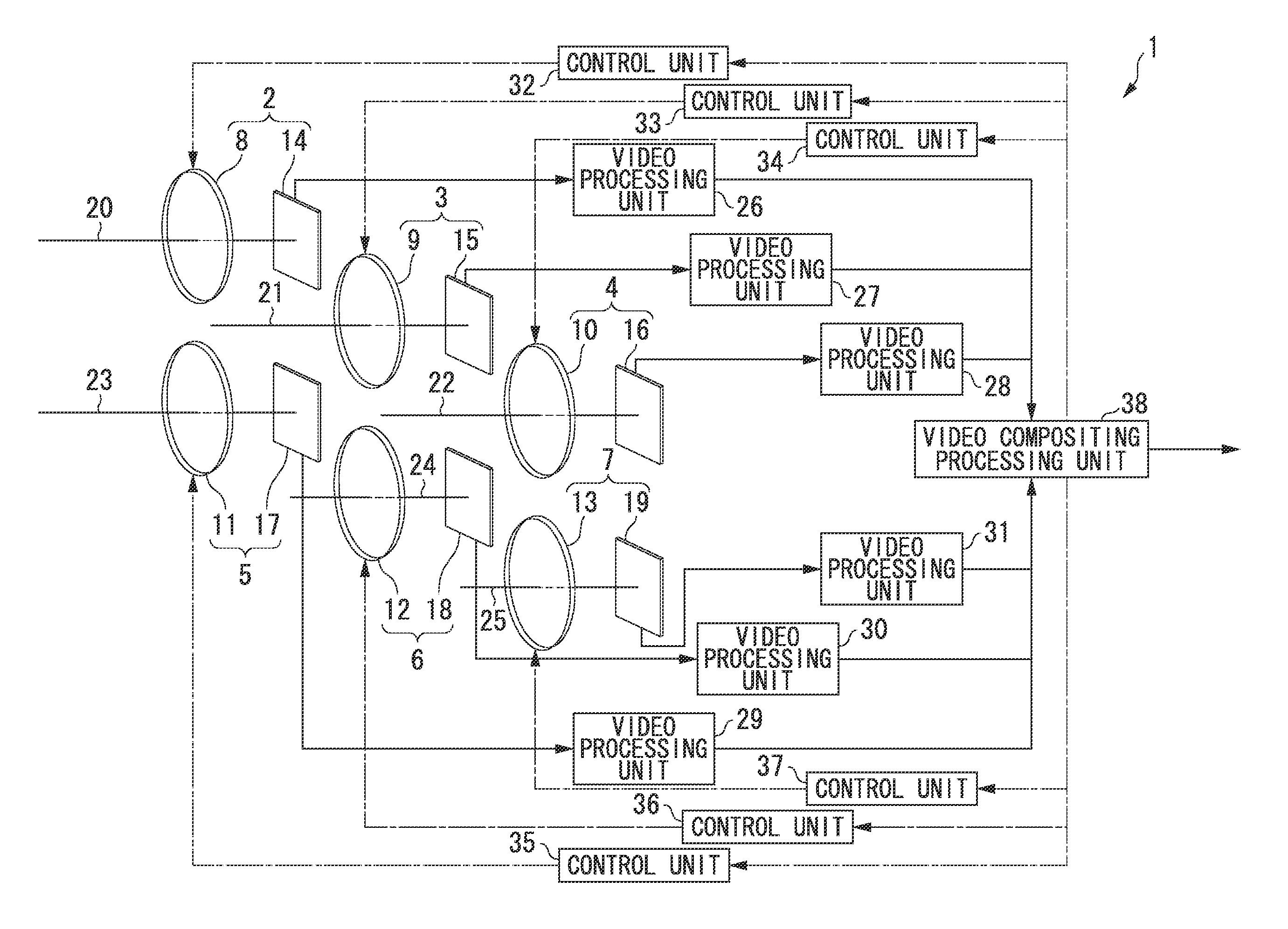
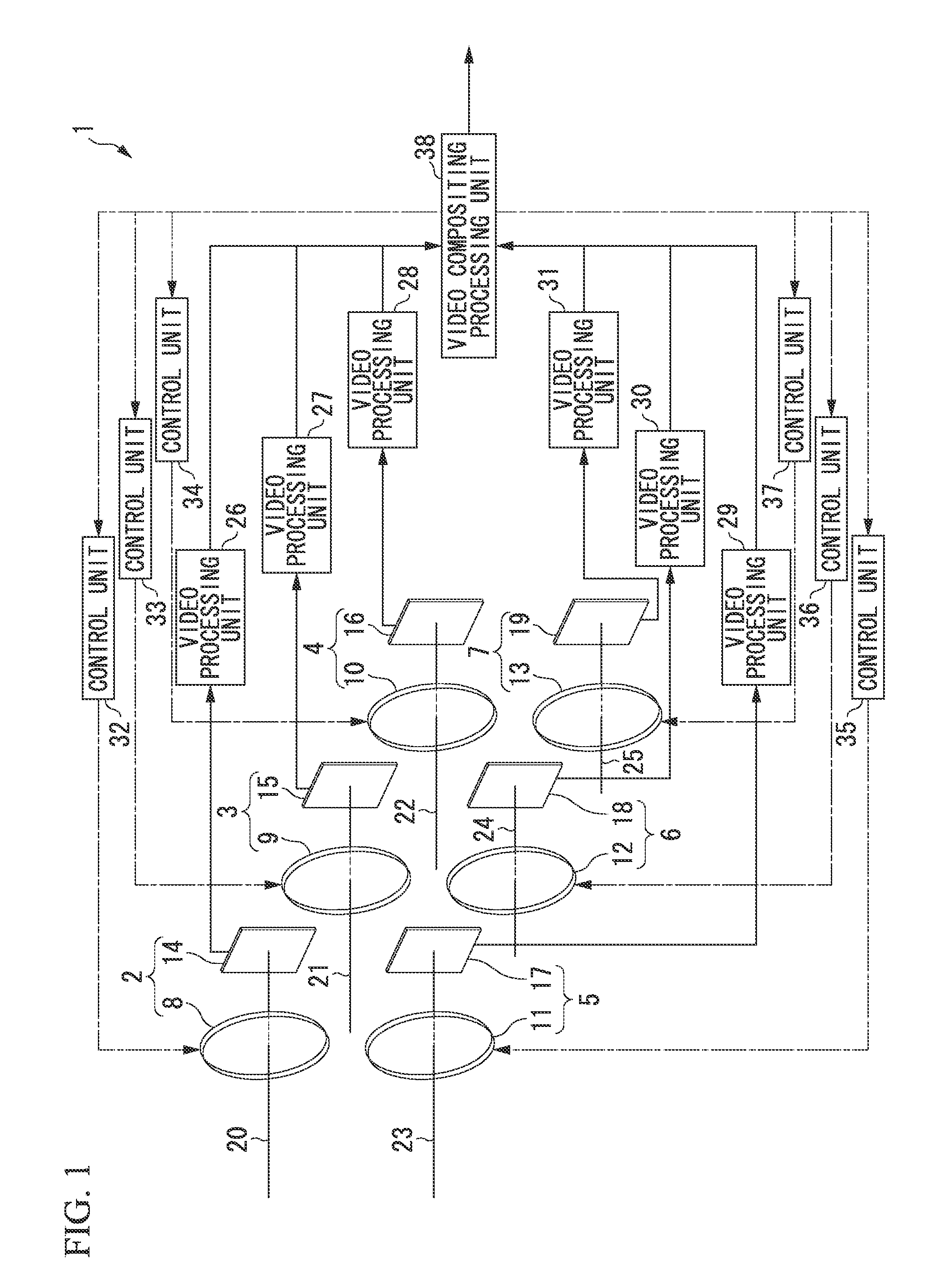
[0068]Embodiments of the present invention are described below in detail, with references made to the drawings. FIG. 1 is a functional block diagram showing the overall constitution of an imaging apparatus according to the first embodiment of the present invention. The imaging apparatus 1 shown in FIG. 1 has six sets of unit imaging units, 2 to 7. The unit imaging unit 2 is formed by an imaging lens 8 and an imaging element 14. Similarly, the unit imaging unit 3 is formed by an imaging lens 9 and an imaging element 15. The unit imaging unit 4 is formed by an imaging lens 10 and an imaging element 16. The unit imaging unit 5 is formed by an imaging lens 11 and an imaging element 17. The unit imaging unit 6 is formed by an imaging lens 12 and an imaging element 18. The unit imaging unit 7 is formed by an imaging lens 13 and an imaging element 19. Each of the imaging lenses 8 to 13 forms an image from the light from the photographed object onto the corresponding imaging elements 14 to ...


PUM


Abstract

An imaging apparatus includes: a plurality of imaging elements; a plurality of solid lenses that form images on the plurality of imaging elements; a plurality of optical axis control units that control the directions of the optical axes of light that is incident to each of the plurality of imaging elements; a plurality of video processing units that convert photoelectric converted signals output from each of the plurality of imaging elements to video signals; a stereo image processing unit that, by performing stereo matching processing based on the plurality of video signals converted by the plurality of video processing units, determines the amount of shift for each pixel, and generates compositing parameters in which the shift amounts that exceed the pixel pitch of the plurality of imaging elements are normalized to the pixel pitch; and a video compositing processing unit that generates high-definition video by compositing the video signals converted by the plurality of video processing units, based on the compositing parameters generated by the stereo image processing unit.

Description

TECHNICAL FIELD[0001]The present invention relates to an imaging apparatus and an imaging method.[0002]Priority is claimed based on the Japanese patent application 2009-083276, filed on Mar. 30, 2009, the content of which is incorporated herein by reference.BACKGROUND ART[0003]In recent years, digital still cameras and digital video cameras (hereinafter referred to as digital cameras) with high image quality have seen rapid growth in use. Digital cameras are also undergoing advances in compactness and light weight, and compact digital cameras with high image quality are incorporated into cellular telephone handsets or the like. Imaging apparatuses typically used in digital cameras include an imaging element, an image-forming optical system (lens optical system), an image processor, a buffer memory, a flash memory (card-type memory), an image monitor, and electronic circuits and mechanisms that control these elements. The imaging element used is usually a solid-state electronic devic...

Claims


Application Information

Patent Timeline
Patent Type & Authority Applications(United States)
IPC IPC(8): H04N13/02
CPCG03B35/08H04N1/387H04N5/2258H04N13/0242H04N5/23238H04N5/23293H04N5/3415H04N5/23232H04N13/243H04N23/45H04N23/60H04N23/951H04N23/698H04N25/41
Inventor SATO, SHUNICHI
Owner SHARP KK
Why Eureka
Try Eureka