Air pipe indoor machine

An air duct indoor unit and fan technology, which is applied in the directions of duct layout, space heating and ventilation, space heating and ventilation details, etc. the effect of comfort

Inactive Publication Date: 2014-01-01
GREE ELECTRIC APPLIANCES INC
View PDF7 Cites 6 Cited by
  • Summary
  • Abstract
  • Description
  • Claims
  • Application Information

AI Technical Summary

Problems solved by technology

[0006] The purpose of the present invention is to provide an air duct indoor unit with downward airflow, so as to solve the problem of poor heating comfort of the side wall of the air duct indoor unit

Method used


Image

  • Air pipe indoor machine
  • Air pipe indoor machine
  • Air pipe indoor machine

Examples


Embodiment Construction

[0031] The present invention will be described in detail below with reference to the accompanying drawings and examples.

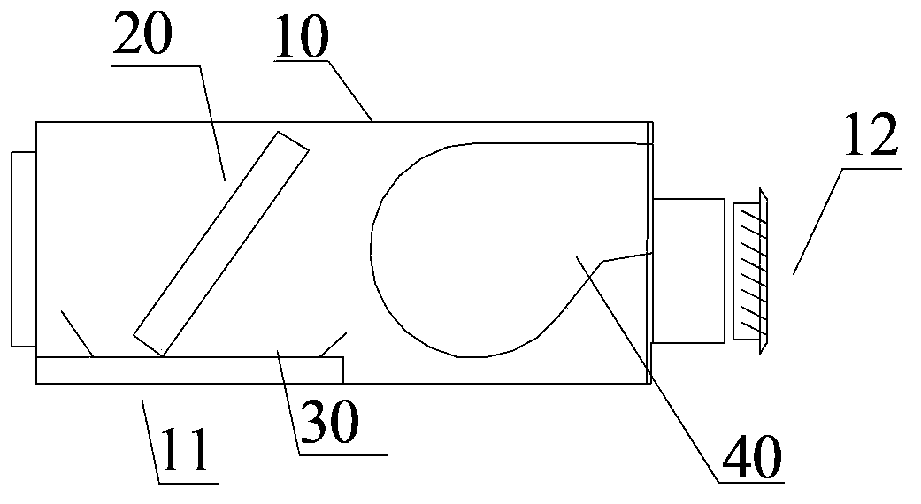
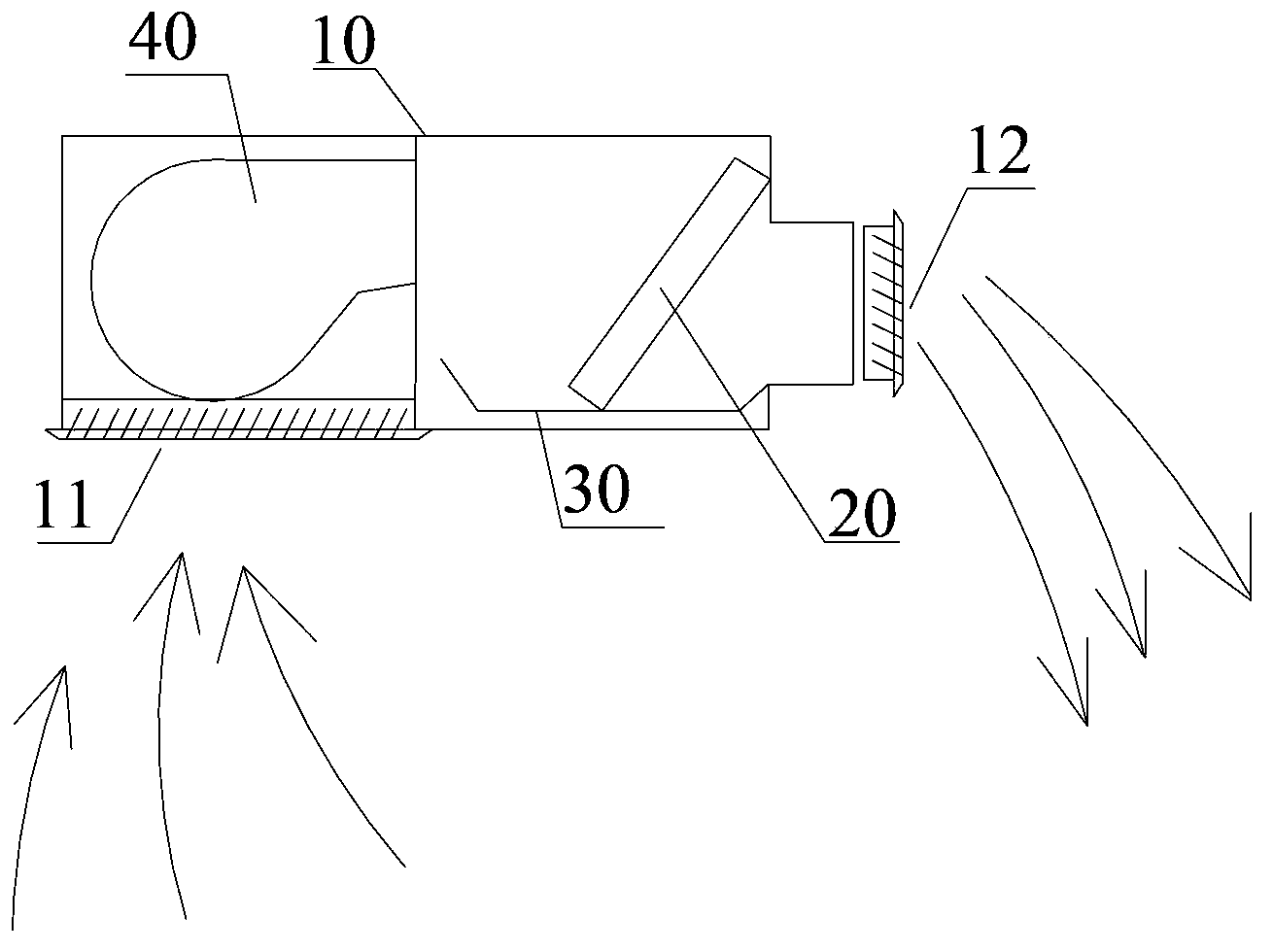
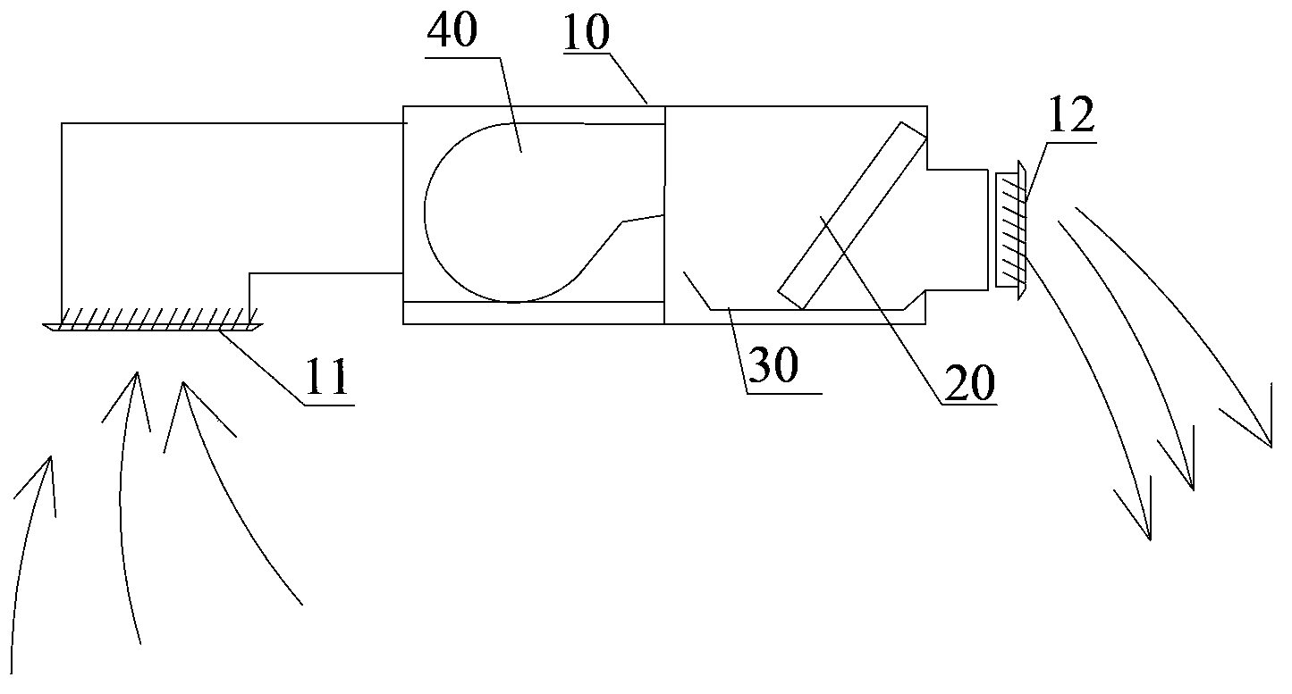
[0032] Such as Figures 5 to 9 As shown, the air duct indoor unit according to the present invention includes a casing 10, and a heat exchanger 20 is fixedly arranged inside the casing 10, a water receiving tray 30 is arranged at the lower part of the heat exchanger 20, and one side of the heat exchanger 20 is arranged There is a fan 40 , and the casing 10 is provided with an air inlet 11 and an air outlet 12 respectively located on both sides of the heat exchanger 20 , and the air outlet 12 is arranged on the lower side wall of the casing 10 . The air outlet is arranged on the lower side wall of the housing 10, so that the air outlet direction of the air duct indoor unit is directly downward, effectively solving the problem that the ordinary air duct indoor unit needs to install an air duct to make the air outlet direction downward , and improve the air ...


PUM


Abstract

The invention provides an air pipe indoor machine. The air pipe indoor machine comprises a shell, wherein the inner part of the shell is fixedly provided with a heat exchanger, the lower part of the heat exchanger is provided with a water pan, one side of the heat exchanger is provided with a draught fan, the shell is provided with an air inlet and an air outlet which are respectively positioned at two sides of the heat exchanger, and the air outlet is arranged on the lower side wall of the shell. According to the air pipe indoor machine provided by the invention, the air outlet is arranged on the lower side wall of the shell, thus an air outlet direction of the air pipe indoor machine is directly enabled to face downwards, the problem that the downward air outlet direction of a common small-sized household air pipe indoor machine can be realized by installing an air pipe on the common small-sized household air pipe indoor machine is effectively solved, and the air outlet efficiency and the heating comfort are increased.

Description

technical field [0001] The invention relates to the field of air duct machines, in particular to an air duct indoor unit. Background technique [0002] In terms of unit structure, the household small air duct indoor units currently on the market are as follows: Figure 1 to Figure 4 As shown, it mainly includes a housing 10, a heat exchanger 20 is fixed inside the housing 10, a water receiving tray 30 is provided below the heat exchanger 20, a fan 40 is provided on one side of the heat exchanger 20, and a fan 40 is provided on the housing 10. An air inlet 11 and an air outlet 12 located on both sides of the heat exchanger 20 are provided. From the perspective of airflow organization, there are mainly the following forms: [0003] side send next time, such as figure 1 and figure 2 As shown, the air inlet 11 of the air duct indoor unit is designed at the lower part of the indoor unit, and the air outlet 12 of the air duct indoor unit is designed at the side of the indoor ...

Claims


Application Information

Patent Timeline
Patent Type & Authority Applications(China)
IPC IPC(8): F24F1/00F24F13/30F24F13/06
Inventor 苏玉海杜辉晋加伟陈慧王成周伙喜
Owner GREE ELECTRIC APPLIANCES INC
Why Eureka
Try Eureka