Indoor unit

An indoor unit and fan technology, which is applied in the field of indoor units, can solve the problems of poor heating comfort and poor wind-to-noise ratio by the side of the indoor unit, and achieve the effects of improving efficiency and comfort, reducing noise, and improving wind-to-noise ratio.

Active Publication Date: 2014-01-01
GREE ELECTRIC APPLIANCES INC
View PDF5 Cites 4 Cited by
  • Summary
  • Abstract
  • Description
  • Claims
  • Application Information

AI Technical Summary

Problems solved by technology

[0006] The present invention aims to provide an indoor unit with downward airflow and improved wind-to-noise ratio, so as to solve the problems of poor heating comfort and relatively poor wind-to-noise ratio of indoor units

Method used


Image

  • Indoor unit
  • Indoor unit
  • Indoor unit

Examples


Embodiment Construction

[0037] The present invention will be described in detail below with reference to the accompanying drawings and examples.

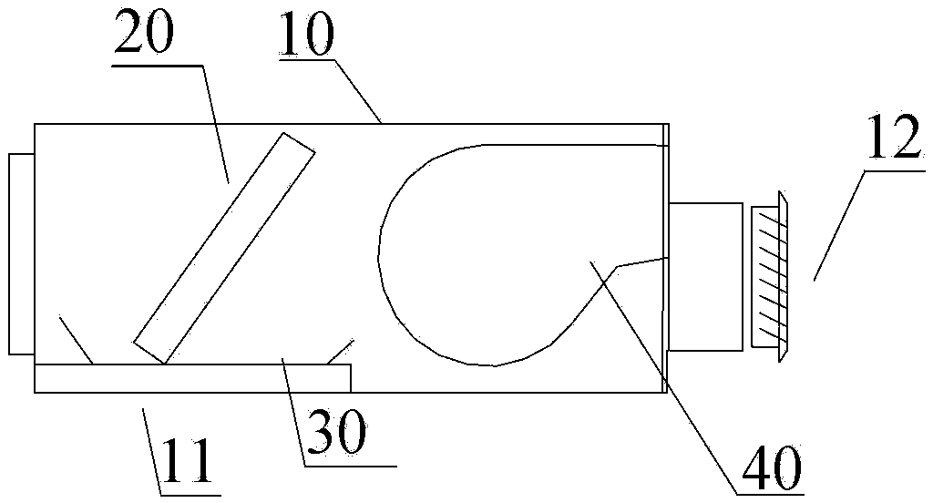
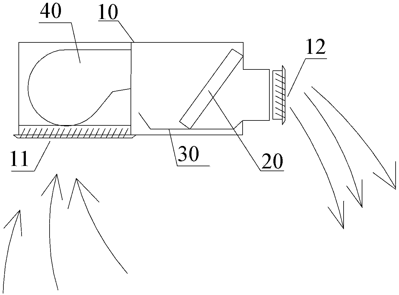
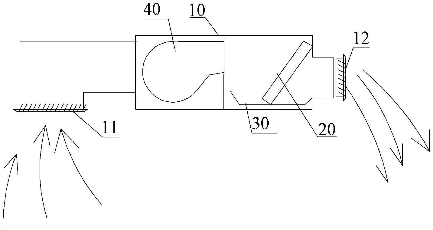
[0038] Such as Figures 5 to 7 As shown, the indoor unit according to the present invention (taking the air duct indoor unit as an example) includes a housing 10, a fan 40 is fixed inside the housing 10, a heat exchanger 20 is arranged on the air inlet side of the fan 40, and a heat exchanger 20 is arranged on the housing 10. An air return port 11 and an air outlet 12 respectively located on both sides of the heat exchanger 20 are provided, and the air return port 11 is arranged on the rear side, or the upper side, or both of the rear side and the upper side of the housing 10 , the fan 40 is a cross-flow fan, and the diffuser 43 of the cross-flow fan is arranged downward; the cross-flow fan includes a cross-flow wind wheel 41 and a volute 42 arranged in cooperation with each other, and the volute 42 is co-located inside the housing 10; the volute 42 inclu...


PUM


Abstract

The utility model provides an indoor unit, which comprises a housing and is characterized in that a fan is fixedly arranged inside the housing; a heat exchanger is arranged at an air intake side of the fan; the housing is provided with an air return port and an air outlet respectively located at both sides of the heat exchanger; the air return port is formed in the rear side face or the upper side face of the housing, or the air return ports are formed in rear side face and the upper side face of the housing at the same time; the fan is a cross-flow fan, and a diffusion part of the cross-flow fan is arranged downwards; the cross-flow blower comprises a cross-flow wind wheel and a volute which are arranged in a mutual cooperative way, and the volute is cooperatively arranged inside the housing; the volute comprises a front volute forming a first side face of the diffusion part and a back volute forming a second side face of the diffusion part; the minimal clearance between the edge of the cross-flow wind wheel and the front volute is delta 1, wherein delta 1 is larger than or equal to 3mm and smaller than or equal to 13mm; and the minimum clearance between the edge of the cross-flow wind wheel and the back volute is delta 2, wherein delta 2 is larger than or equal to 3mm and smaller than or equal to 15mm. According to the utility model, the air outlet direction is directly downward, and the air noise ratio is improved.

Description

technical field [0001] The invention relates to the field of air conditioners, in particular to an indoor unit. Background technique [0002] In terms of unit structure, the household small indoor units currently on the market (take the air duct indoor unit as an example) are as follows: Figure 1 to Figure 4 As shown, it mainly includes a housing 10, a heat exchanger 20 is fixed inside the housing 10, a water receiving tray 30 is provided below the heat exchanger 20, a fan 40 is provided on one side of the heat exchanger 20, and a fan 40 is provided on the housing 10. An air return port 11 and an air outlet 12 located on both sides of the heat exchanger 20 are provided. From the perspective of airflow organization, there are mainly the following forms: [0003] side send next time, such as figure 1 and figure 2 As shown, the air return port 11 of the indoor unit is designed at the lower part of the indoor unit, and the air outlet 12 of the indoor unit is designed at th...

Claims


Application Information

Patent Timeline
Patent Type & Authority Applications(China)
IPC IPC(8): F24F1/00F04D29/42
Inventor 苏玉海王成杜辉冯汇远岳耀标旷文琦
Owner GREE ELECTRIC APPLIANCES INC
Why Eureka
Try Eureka