Shaft furnace cooling air pipeline system

A pipeline system and cooling gas technology, which is applied in the shaft furnace cooling gas pipeline system and the recovery of shaft furnace cooling gas, can solve cooling and other problems, and achieve the effects of enhanced gas collection, high gas recovery, and simple pipeline manufacturing

Pending Publication Date: 2017-08-22
JIANGSU PROVINCE METALLURGICAL DESIGN INST
View PDF0 Cites 0 Cited by
  • Summary
  • Abstract
  • Description
  • Claims
  • Application Information

AI Technical Summary

Problems solved by technology

In addition to the ring pipe, the gas collection pipeline is also equipped with a central branch pipe, which solves the problem of cooling gas collection in the center of the large-sized furnace

Method used


Image

  • Shaft furnace cooling air pipeline system
  • Shaft furnace cooling air pipeline system
  • Shaft furnace cooling air pipeline system

Examples


Embodiment 1

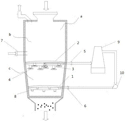
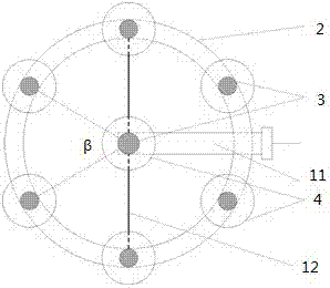
[0058] Install the gas receiving ring pipe horizontally on the inner wall of the shaft furnace and connect it with the cooling gas outlet of the shaft furnace. The cooling gas inlet of the shaft furnace is connected with the inlet ring pipe. The air ring pipe is connected with the air receiving ring pipe, the other end is provided with the air receiving pipe, the air receiving pipe provided on the central branch pipe is located in the middle of the air receiving ring pipe, and one end of each support member is vertically fixed on the The other end of the lower part of the central branch pipe is connected to the inner wall of the shaft furnace or the gas receiving ring pipe, and the inlet ring pipe is horizontally arranged on the inner wall of the shaft furnace; the outlet of the cooling gas and the inlet of the cooling gas both extend to the outside of the shaft furnace The gas collection ring is located at the top of the cooling section of the shaft furnace, and is lower than ...

Embodiment 2

[0063]Install the gas receiving ring pipe horizontally on the inner wall of the shaft furnace and connect it with the cooling gas outlet of the shaft furnace. The cooling gas inlet of the shaft furnace is connected with the inlet ring pipe. The air ring pipe is connected with the air receiving ring pipe, the other end is provided with the air receiving pipe, the air receiving pipe provided on the central branch pipe is located in the middle of the air receiving ring pipe, and one end of each support member is vertically fixed on the The other end of the lower part of the central branch pipe is connected to the inner wall of the shaft furnace or the gas receiving ring pipe, and the inlet ring pipe is horizontally arranged on the inner wall of the shaft furnace; the outlet of the cooling gas and the inlet of the cooling gas both extend to the outside of the shaft furnace The gas collection ring is located at the top of the cooling section of the shaft furnace, and is lower than t...


PUM


Abstract

The invention relates to a shaft furnace cooling air pipeline system. The shaft furnace cooling air pipeline system comprises an air inlet annular pipe, an air collecting annular pipe, an air collecting pipe and an air collecting cover; it is ensured that air recovery is more efficient through the design of the cooling air collecting pipe and the cooling air collecting cover, the ratio of cooling air which is not effectively collected and rises to a reduction section of a shaft furnace instead, and the main reaction of the reduction section of the shaft furnace is ensured better. The tail end of the air collecting pipe is closed, multiple holes are formed in the pipe walls, and blockage of the cooling air collecting pipeline is eliminated on the premise of not affecting the air collecting effect. By means of the design of an air inlet pipeline and air collecting pipeline system, smooth discharging of furnace burden is not affected, air is input through multiple openings of the air inlet pipe to ensure uniform distribution of the inlet air, the air collecting cover is directly welded to the outside of the air collecting pipe to enhance the air collecting effect without obviously blocking direct motion of a sponge iron product, and the pipelines are easy to manufacture and convenient to obtain. A center branch is arranged besides the annular pipes, and the problem of collecting the cooling air in the center of a large-size combustion chamber is solved.

Description

technical field [0001] The invention belongs to the technical field of metallurgy, and in particular relates to recovery of cooling gas of a shaft furnace, in particular to a cooling gas piping system of a shaft furnace. Background technique [0002] Gas-based shaft furnace direct reduction ironmaking is the most important non-blast furnace ironmaking method, and its product is direct reduced iron (also known as sponge iron), which is mainly used as raw material for electric furnace steelmaking, and can also be used as a coolant for converter steelmaking. Gas-based shaft furnace uses CO and H 2 As the raw material of reducing gas, iron oxide-containing minerals are reduced in the shaft furnace to obtain products. The inside of the shaft furnace is usually divided into three parts from top to bottom, preheating section, reducing section and cooling section. Reducing gas is introduced into the furnace from the middle of the shaft furnace, and ore raw materials are fed from t...

Claims


Application Information

Patent Timeline
Patent Type & Authority Applications(China)
IPC IPC(8): C21B13/02
CPCY02P10/143C21B13/02
Inventor 吴道洪刘亮邓君范志辉员晓唐敬坤冯鲁兴韩志彪
Owner JIANGSU PROVINCE METALLURGICAL DESIGN INST
Why Eureka
Try Eureka