An anti-icing evaporator coil structure

An evaporator coil, anti-icing technology, applied in the direction of evaporator/condenser, heat exchanger shell, refrigerator, etc., can solve the problems of coil structure damage, coil shaking, evaporator loosening, etc., to prevent The effect of supercooling and freezing, improving adaptability, and improving practicality

Active Publication Date: 2021-08-10
ZHONGCHUAN NO 9 DESIGN & RES INST
View PDF17 Cites 0 Cited by
  • Summary
  • Abstract
  • Description
  • Claims
  • Application Information

AI Technical Summary

Problems solved by technology

[0003] The invention provides an anti-icing evaporator coil structure, which has the advantages of being able to balance the temperature of each part of the coil, providing support for the coil and preventing the coil from shaking due to external force, and solves the problem of low temperature environment. It will directly cause the evaporator coil to be partially overcooled or even freeze when the refrigerant continues to absorb heat. In severe cases, it will cause damage to the evaporator coil. The specific coil support devices are all temporary supports for the coil, which will lead to low stability of the coil, and will cause the coil to be damaged due to the slowing of the water flow rate or the action of external forces during the use of the coil. The shaking of the coil will make the direct connection between the coil and the evaporator loose under the action of the shaking, and the structure of the coil will be damaged, so that the evaporator cannot operate normally, and if the damaged coil is not replaced for a long time, it will also cause The problem of security incidents

Method used


Image

  • An anti-icing evaporator coil structure
  • An anti-icing evaporator coil structure
  • An anti-icing evaporator coil structure

Examples


Embodiment Construction

[0023] The following will clearly and completely describe the technical solutions in the embodiments of the present invention with reference to the accompanying drawings in the embodiments of the present invention. Obviously, the described embodiments are only some, not all, embodiments of the present invention. Based on the embodiments of the present invention, all other embodiments obtained by persons of ordinary skill in the art without making creative efforts belong to the protection scope of the present invention.

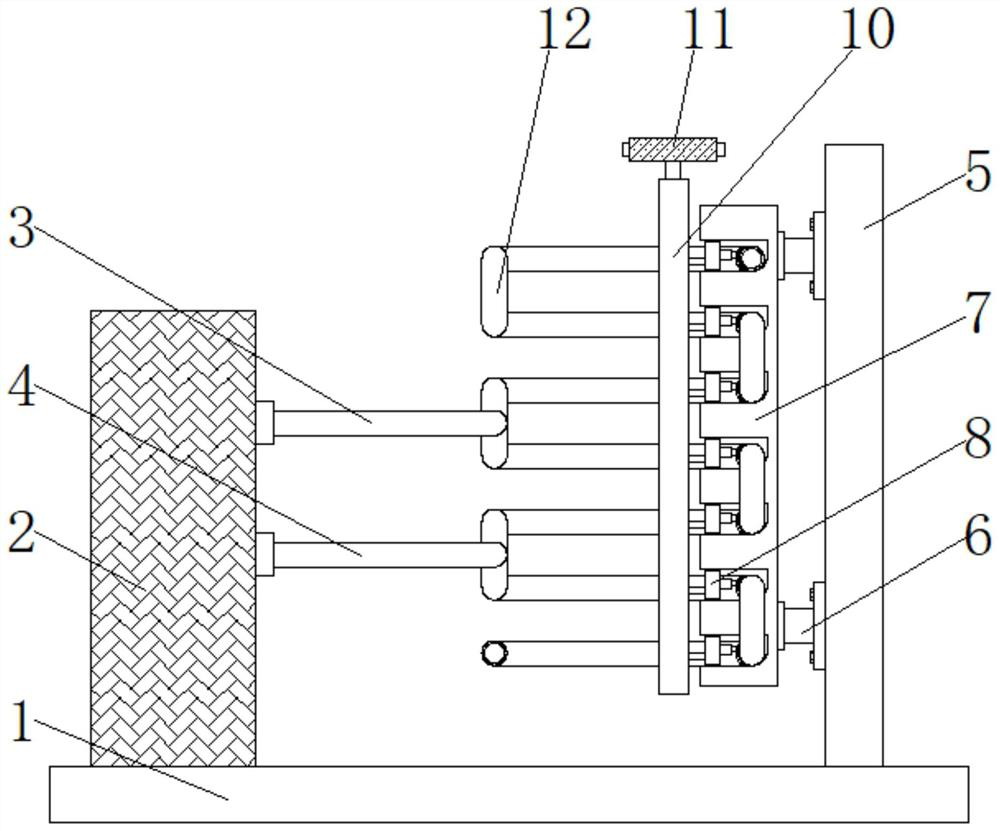
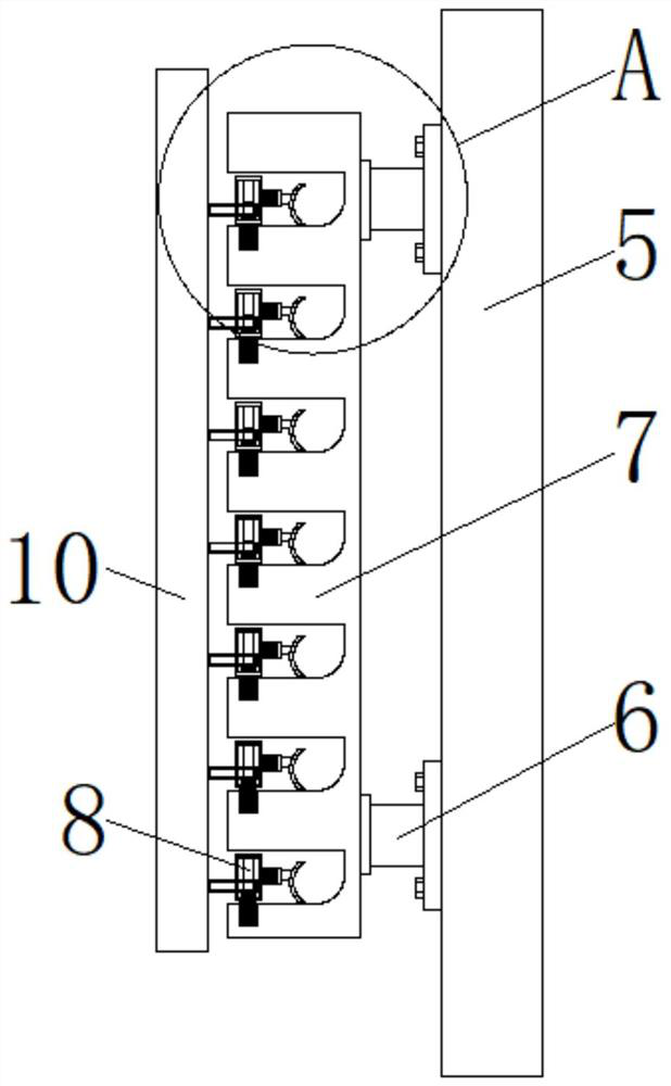
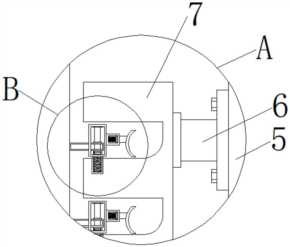
[0024] see Figure 1-6, an anti-freezing evaporator coil structure, including a bottom plate 1, a locking device 8, a limiting device 9 and a coil body 12, the locking device 8 includes a telescopic rod 803, and the bottom end of the telescopic rod 803 runs through the left side of the locking plate 7 The bottom surface of the side groove extends to the inside of the locking plate 7, the top of the telescopic rod 803 is movably socketed with a locking box 801,...


PUM


Abstract

The invention relates to the technical field of evaporator coils, and discloses an anti-freezing evaporator coil structure, which includes a bottom plate, a locking device, a limiting device and a coil body, and a water circulation device is fixedly installed on the left end of the top surface of the bottom plate. The top of the right side of the water circulation device is fixedly connected with a water inlet pipe, the middle part of the right side of the water circulation device is fixedly connected with a water outlet pipe, and the other end of the water inlet pipe is fixedly connected with the middle part of the outer surface of the coil body. The anti-freezing evaporator coil structure, through the setting of the water circulation device, can rely on the communication relationship between the inlet and outlet pipes and the coil body, so that the flow of water will not be received when the inlet temperature of the evaporator is lower than the design. When the temperature is fixed, the water circulation device is started, and the water is introduced and drawn out from the water inlet pipe and the water outlet pipe to ensure that this part of the water is in a flowing state, and the temperature of each part of the coil body is balanced to effectively prevent supercooling and freezing, thereby improving the performance of the evaporator. Coil usability.

Description

technical field [0001] The invention relates to the technical field of evaporator coils, in particular to an anti-freezing evaporator coil structure. Background technique [0002] The air compressor station is one of the main energy-consuming stations of the shipyard. It generates a large amount of surplus heat energy during its operation. Necessary measures must be taken to remove this part of the energy so as not to affect the normal operation of the unit. The traditional method is to use water as the carrier To take out the heat and discharge it into the atmosphere in the mode of cooling water tower, a certain amount of electric energy needs to be input in the process. According to the actual operation of the air compressor, it can be inferred that the extreme working condition encountered by the evaporating side of the unit is "winter Superposition of low water temperature and low load operation of the air compressor”, at this time, due to the low base water temperature ...

Claims


Application Information

Patent Timeline
Patent Type & Authority Patents(China)
IPC IPC(8): F25B39/02F28F9/013F28F9/26
CPCF25B39/02F25B2339/02F25B2500/13F28F9/0131F28F9/26
Inventor 杨浩俊陈浩高国瑜朱凯孙伟军李建红
Owner ZHONGCHUAN NO 9 DESIGN & RES INST
Why Eureka
Try Eureka