Check patentability & draft patents in minutes with Patsnap Eureka AI!

Laser cladding device

A technology of laser cladding and mounting frame, applied in metal material coating process, coating and other directions, can solve the problems of low dilution of cladding layer, affecting the quality of cladding, strong bonding force, etc.

Active Publication Date: 2020-09-29
江苏智远激光装备科技有限公司
View PDF6 Cites 2 Cited by
  • Summary
  • Abstract
  • Description
  • Claims
  • Application Information

AI Technical Summary

Problems solved by technology

[0002] Laser cladding (Laser cladding), also known as laser cladding or laser cladding, is a new surface modification technology; The method of melting and coagulating the thin layers on the surface of the material forms a metallurgically bonded cladding layer on the surface of the base layer, and the resulting cladding layer has low dilution but strong bonding force, and is metallurgically bonded to the substrate, which can significantly improve the surface of the substrate material. Wear resistance, corrosion resistance, heat resistance, oxidation resistance or electrical properties, so as to achieve the purpose of surface modification or repair, meet the specific performance requirements of the material surface and save a lot of material costs; and surfacing, spraying, electroplating and vapor deposition In comparison, laser cladding has the characteristics of small dilution, dense structure, good combination of coating and substrate, many materials suitable for cladding, and large changes in particle size and content. Therefore, the application prospect of laser cladding technology is very broad; but currently for slender In the cladding technology of shaft parts, since the fixture is generally clamped on both ends of the shaft by the fixture when fixing the part, a certain degree of bending deformation will be formed due to the influence of gravity in the middle of the slender shaft itself, especially When the laser cladding head is cladding from one end to the other, the heat generated will also aggravate such deformation, which will cause uneven thickness during the cladding operation and affect the quality of cladding

Method used


Image

  • Laser cladding device
  • Laser cladding device
  • Laser cladding device

Examples


Embodiment Construction

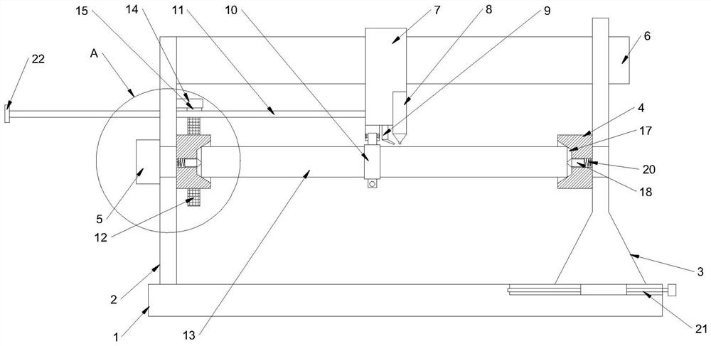
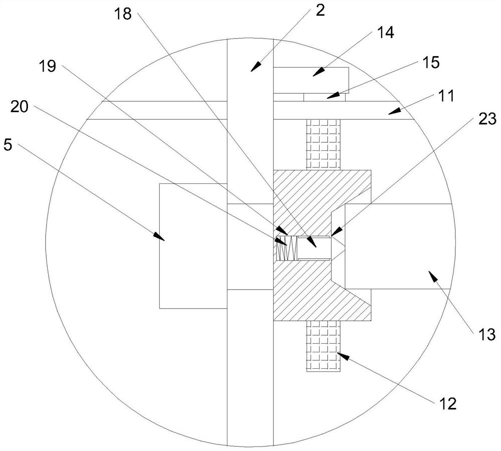
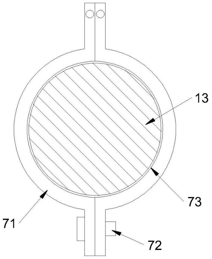
[0021] combine Figure 1 to Figure 5 The laser cladding device shown in this embodiment includes a base 1, a mounting frame, a fixture body 4, a rotating motor 5, a guide frame 6, a carriage 7, a laser cladding head 8, a powder feeding pipe 9, Support hoop 10, guide arc plate 11 and annular thread block 12; two sets of mounting frames are arranged on the base 1, and two sets of fixture bodies 4 are respectively rotatably connected to the two sets of mounting frames, and can be installed on one of the mounting frames Driven by the rotating motor 5 above, the two ends of the shaft workpiece 13 are held tightly to rotate; the guide frame 6 is erected horizontally between the two sets of mounting frames, and the carriage 7 is horizontally slidably connected to the guide frame 6, and the laser cladding head 8 The powder feeding tube 9 that can be aligned towards the surface of the workpiece 13 that can be aligned with the laser cladding head 8 is installed on the carriage 7; the su...


PUM


Abstract

The invention provides a laser cladding device. The laser cladding device comprises a base, mounting racks, clamp bodies, a rotating motor, a guiding rack, a sliding rack, a laser cladding head, a powder feeding pipe, a supporting hoop, a guiding arc plate and an annular threaded block; the two mounting racks are arranged on the base, the two clamp bodies are rotationally connected onto the two mounting racks respectively, the guiding rack is horizontally arranged between the two mounting racks, the sliding rack is connected onto the guiding rack in a horizontal sliding manner, and the supporting hoop comprises two hoop units hinged to the bottom of the sliding rack, bolts for closed connection of the bottom ends of the two hoop units and sliding surfaces located on the inner sides of thetwo hoop units; one clamp body is sleeved and fixed with the annular threaded block, an external thread is formed in the circumferential outer wall of the annular threaded block, at least one guidingarc plate is arranged, and an internal thread matched with the external thread is formed in the arc inner side wall of the at least one guiding arc plate. The laser cladding device is simple in structure, and has low probability of causing the phenomenon of uneven cladding under influence of clamping by two ends of a slender shaft part or cladding heat deformation.

Description

technical field [0001] The invention relates to a cladding device, in particular to a laser cladding device. Background technique [0002] Laser cladding (Laser cladding), also known as laser cladding or laser cladding, is a new surface modification technology; The method of melting and coagulating the thin layers on the surface of the material forms a metallurgically bonded cladding layer on the surface of the base layer, and the resulting cladding layer has low dilution but strong bonding force, and is metallurgically bonded to the substrate, which can significantly improve the surface of the substrate material. Wear resistance, corrosion resistance, heat resistance, oxidation resistance or electrical properties, so as to achieve the purpose of surface modification or repair, meet the specific performance requirements of the material surface and save a lot of material costs; and surfacing, spraying, electroplating and vapor deposition In comparison, laser cladding has the...

Claims


Application Information

Patent Timeline
IPC IPC(8): C23C24/10
CPCC23C24/10
Inventor 林学春农光壹林培晨杭骏祥
Owner 江苏智远激光装备科技有限公司
Features
  • R&D
  • Intellectual Property
  • Life Sciences
  • Materials
  • Tech Scout
  • Unparalleled Data Quality
  • Higher Quality Content
  • 60% Fewer Hallucinations
Learn More