Magnetic track brake application control system and method

A technology of magnetic rail braking and control system, which is applied in the direction of railway braking system, braking components interacting with rails, transportation and packaging, etc. The effect of improving ride comfort

Active Publication Date: 2020-10-16
ZHUZHOU ELECTRIC LOCOMOTIVE CO
View PDF6 Cites 2 Cited by
  • Summary
  • Abstract
  • Description
  • Claims
  • Application Information

AI Technical Summary

Problems solved by technology

[0011]In the prior art, since the magnetic rail braking force suddenly changes at the moment when the magnetic rail braking application command is issued, the impact on the vehicle at the moment of the magnetic rail braking application Larger, affecting the ride comfort of passengers

Method used


Image

  • Magnetic track brake application control system and method
  • Magnetic track brake application control system and method
  • Magnetic track brake application control system and method

Examples


Embodiment Construction

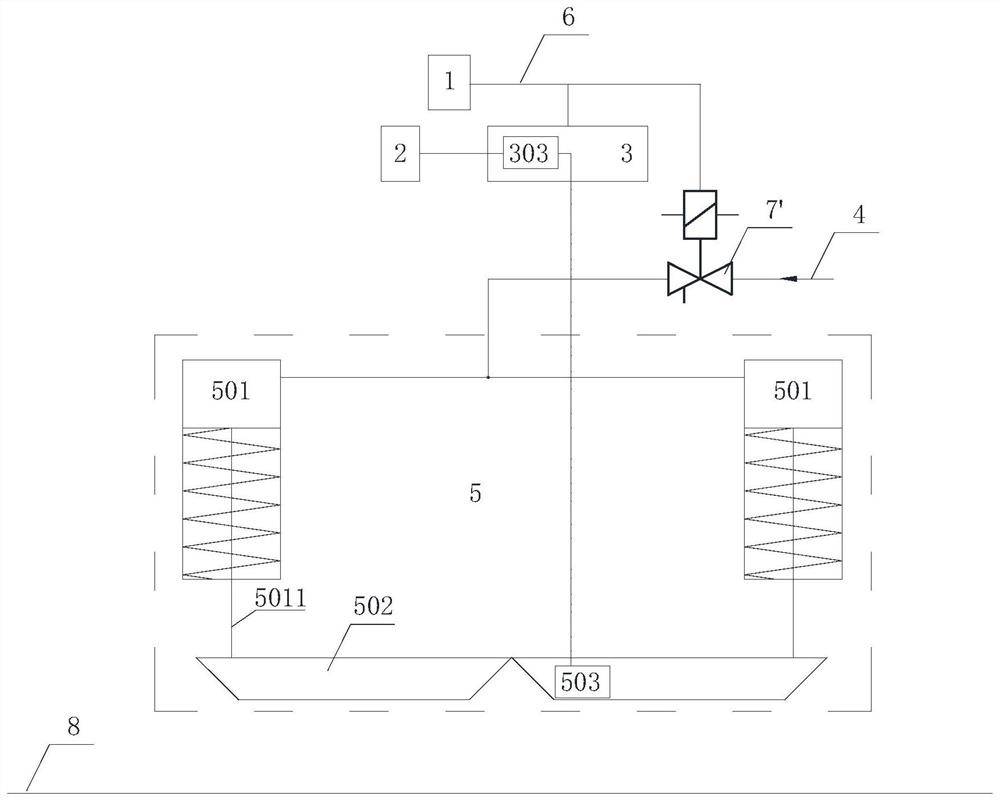
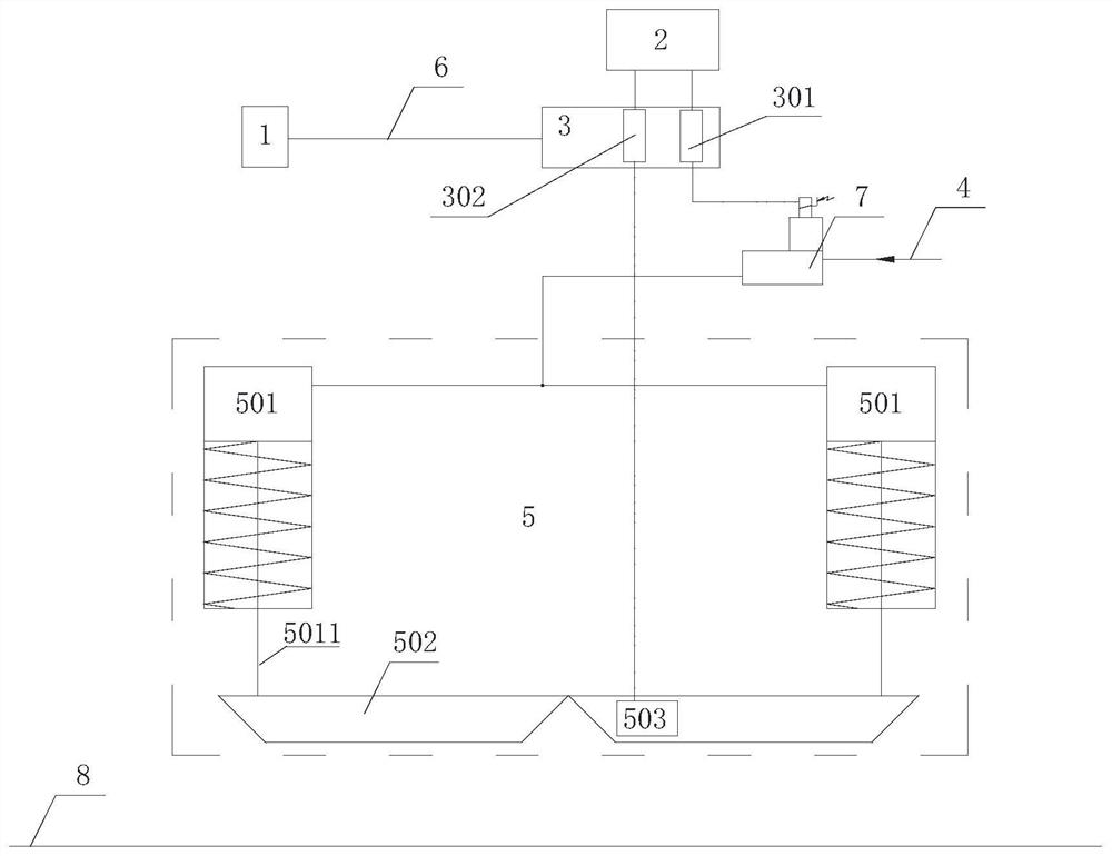
[0037] Such as figure 2As shown, the magnetic track brake application control system of the present invention includes a brake microcomputer unit 1, a brake power supply 2, a magnetic track brake control unit 3, a brake pipe 4, and a magnetic track brake 5; the magnetic track brake 5 includes a cylinder 501 and pole shoe 502, wherein the piston rod 5011 of the cylinder 501 is fixedly connected to the pole shoe 502, and the pole shoe 502 is provided with an excitation coil 503; the input end of the magnetic track brake control unit 3 is connected with the magnetic track brake command line 6 The output end of the brake microcomputer unit 1 is electrically connected; the magnetic track brake control unit 3 is used to receive the magnetic track brake application instruction from the brake microcomputer unit 1 .

[0038] The magnetic rail brake application control system also includes a normally closed analog electropneumatic valve 7; the brake pipe 4 is connected to the intake en...


PUM


Abstract

The invention discloses a magnetic track brake application control system and method. The control system comprises a brake microcomputer unit, a brake power supply, a magnetic track brake control unit, a brake pipe and a magnetic track brake; the magnetic track brake comprises an air cylinder and a pole shoe; a piston rod of the air cylinder is fixedly connected with the pole shoe; and the controlsystem further comprises a normally-closed analog electric pneumatic valve. The magnetic track brake control unit is provided with a first current linear amplification unit and a second current linear amplification unit; the brake power supply is electrically connected with the control end of the analog electric pneumatic valve through the first current linear amplification unit; the brake pipe is connected with the air inlet end of the air cylinder through the analog electric pneumatic valve; and the brake power supply is electrically connected with a magnet exciting coil in the pole shoe through the second current linear amplification unit. When magnetic rail braking is applied, the air pressure of the air supply pipeline of the air cylinder is controlled to be linearly increased so asto control the falling speed of the pole shoe, meanwhile, linear current is output to the magnet exciting coil, it is guaranteed that a vehicle cannot generate large impact when magnetic rail brakingis switched on, and the riding comfort of passengers is improved.

Description

technical field [0001] The invention belongs to the technical field of rail vehicle brake control, in particular to a magnetic rail brake application control system and control method. Background technique [0002] Such as figure 1 As shown, the high suspension magnetic rail brake 5 includes a cylinder 501 and a pole piece 502 , wherein the piston rod 5011 of the cylinder 501 is fixedly connected to the pole piece 502 , and the pole piece 502 is provided with an excitation coil 503 . [0003] For EMUs equipped with high-suspension magnetic rail brakes 5, the structure of the existing magnetic rail brake application control system is as follows: figure 1 As shown, it includes a brake microcomputer unit 1, a brake power supply 2, a magnetic rail brake control unit 3, a brake pipe 4, a normally closed digital electropneumatic valve 7'; the input end of the magnetic rail brake control unit 3 and the control end of the digital electro-pneumatic valve 7' are electrically connect...

Claims


Application Information

Patent Timeline
Patent Type & Authority Applications(China)
IPC IPC(8): B61H7/08
CPCB61H7/08
Inventor 阳靖孙宪红梅劲华李振民徐江平
Owner ZHUZHOU ELECTRIC LOCOMOTIVE CO
Why Eureka
Try Eureka