
Uplink full power transmission method and device
A transmission method and full power technology, which is applied in the field of uplink full power transmission method and equipment, can solve problems such as the inability to ensure UE uplink full power transmission, and achieve the effects of full power transmission, enhanced uplink coverage, and uplink transmission power improvement
- Summary
- Abstract
- Description
- Claims
- Application Information
AI Technical Summary
Problems solved by technology
Method used
Image

Examples
Embodiment 1
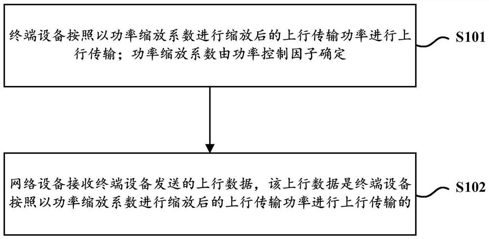
[0043] Assume that the uplink power before scaling calculated by the uplink power control is P, the power scaling factor for uplink transmission is α, and the number of non-zero (or non-zero) antenna ports for uplink transmission is β. Wherein, the non-zero (or non-zero) uplink transmission antenna port means that all row values in the precoding codebook corresponding to the antenna port are non-zero.
[0044] When the terminal device supports the first UE capability (for example, each radio frequency branch of the terminal device supports full power transmission), the power scaling factor may be determined to be 1, that is, α=1.
[0045] After determining the power scaling factor = 1, the terminal device first scales the uplink power P according to the power scaling factor α, and then equally divides it among the non-zero uplink transmission antenna ports to obtain the uplink transmission power of each uplink transmission antenna port (that is, the actual transmission power ...
Embodiment 2
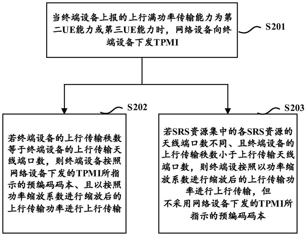
[0048] Assume that the uplink power before scaling calculated by the uplink power control is P, the power scaling factor for uplink transmission is α, and the number of non-zero (or non-zero) antenna ports for uplink transmission is β. Wherein, the non-zero (or non-zero) uplink transmission antenna port means that the row values in the precoding codebook corresponding to the antenna port are all non-zero, which may be referred to as the number of non-zero antenna ports hereinafter.
[0049] When the terminal device supports the second UE capability (for example, each radio frequency branch of the terminal device does not support full power transmission), the value of the power scaling factor α is different according to the working mode supported by the UE.
[0050] Specifically, when the UE supports working mode one (for example, the terminal device reports the working mode one, and the number of antenna ports of each SRS resource in the SRS resource set configured by the net...
Embodiment 3
[0055] Assume that the uplink power before scaling calculated by the uplink power control is P, the power scaling factor for uplink transmission is α, and the number of non-zero (or non-zero) antenna ports for uplink transmission is β. Wherein, the non-zero (or non-zero) uplink transmission antenna port means that the row values in the precoding codebook corresponding to the antenna port are all non-zero, which may be referred to as the number of non-zero antenna ports hereinafter.
[0056] When the terminal device supports the third UE capability (for example, some radio frequency branches of the terminal device support full power transmission), the value of the power scaling factor α is different according to the working mode supported by the UE.
[0057] Specifically, when the UE supports working mode one (for example, the terminal device reports the working mode one, and the number of antenna ports of each SRS resource in the SRS resource set configured by the network dev...
PUM
 Abstract
Description
Claims
Application Information