Uplink full-power transmission method and equipment

A transmission method and full power technology, which is applied in the field of uplink full power transmission method and equipment, and can solve problems such as inability to ensure UE uplink full power transmission

Active Publication Date: 2020-10-20
VIVO MOBILE COMM CO LTD
View PDF2 Cites 4 Cited by
  • Summary
  • Abstract
  • Description
  • Claims
  • Application Information

AI Technical Summary

Problems solved by technology

[0006] Embodiments of the present invention provide a method and device for uplink full power transmission to solve the problem in the prior art that UE uplink full power transmission cannot be ensured

Method used


Image

  • Uplink full-power transmission method and equipment
  • Uplink full-power transmission method and equipment
  • Uplink full-power transmission method and equipment

Examples


Embodiment 1

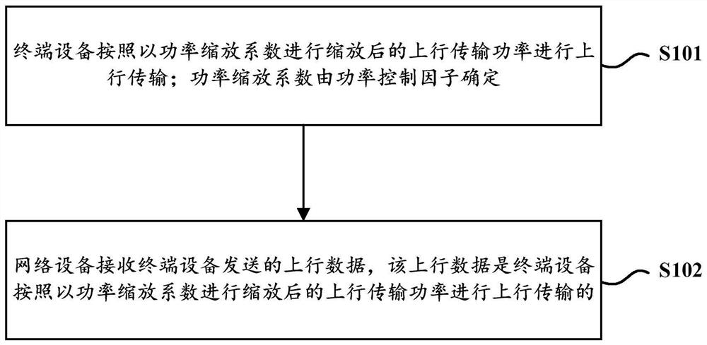
[0043] Assume that the uplink power before scaling calculated by the uplink power control is P, the power scaling factor for uplink transmission is α, and the number of non-zero (or non-zero) antenna ports for uplink transmission is β. Wherein, the non-zero (or non-zero) uplink transmission antenna port means that all row values ​​in the precoding codebook corresponding to the antenna port are non-zero.

[0044] When the terminal device supports the first UE capability (for example, each radio frequency branch of the terminal device supports full power transmission), the power scaling factor may be determined to be 1, that is, α=1.

[0045] After determining the power scaling factor = 1, the terminal device first scales the uplink power P according to the power scaling factor α, and then equally divides it among the non-zero uplink transmission antenna ports to obtain the uplink transmission power of each uplink transmission antenna port (that is, the actual transmission power ...

Embodiment 2

[0048] Assume that the uplink power before scaling calculated by the uplink power control is P, the power scaling factor for uplink transmission is α, and the number of non-zero (or non-zero) antenna ports for uplink transmission is β. Wherein, the non-zero (or non-zero) uplink transmission antenna port means that the row values ​​in the precoding codebook corresponding to the antenna port are all non-zero, which may be referred to as the number of non-zero antenna ports hereinafter.

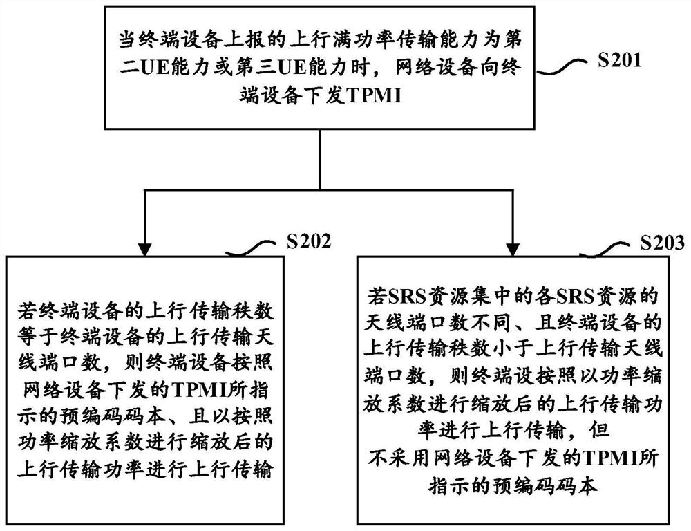
[0049] When the terminal device supports the second UE capability (for example, each radio frequency branch of the terminal device does not support full power transmission), the value of the power scaling factor α is different according to the working mode supported by the UE.

[0050] Specifically, when the UE supports working mode one (for example, the terminal device reports the working mode one, and the number of antenna ports of each SRS resource in the SRS resource set configured by the net...

Embodiment 3

[0055] Assume that the uplink power before scaling calculated by the uplink power control is P, the power scaling factor for uplink transmission is α, and the number of non-zero (or non-zero) antenna ports for uplink transmission is β. Wherein, the non-zero (or non-zero) uplink transmission antenna port means that the row values ​​in the precoding codebook corresponding to the antenna port are all non-zero, which may be referred to as the number of non-zero antenna ports hereinafter.

[0056] When the terminal device supports the third UE capability (for example, some radio frequency branches of the terminal device support full power transmission), the value of the power scaling factor α is different according to the working mode supported by the UE.

[0057] Specifically, when the UE supports working mode one (for example, the terminal device reports the working mode one, and the number of antenna ports of each SRS resource in the SRS resource set configured by the network dev...


PUM


Abstract

The embodiment of the invention discloses an uplink full-power transmission method and uplink full-power transmission equipment, which are used for solving the problem that the uplink full-power transmission of UE (User Equipment) cannot be ensured in the prior art, and the method is applied to terminal equipment and comprises the following steps of: performing uplink transmission according to uplink transmission power scaled by a power scaling coefficient; wherein the power scaling coefficient is determined by a power control factor; wherein the power control factor comprises at least one ofthe following items: the uplink full-power transmission capability of the terminal equipment, a supported transmission precoding matrix indicator (TPMI) reported by the terminal equipment, a TPMI issued by the network equipment, and a working mode reported by the terminal equipment, and the number of antenna ports of each SRS resource in a sounding reference signal SRS resource set configured by the network equipment according to the working mode. According to the technical scheme, the uplink transmission power is improved, the uplink coverage is enhanced, and the uplink full-power transmission of the terminal equipment is realized.

Description

technical field [0001] The present invention relates to the technical field of wireless communication, in particular to an uplink full power transmission method and equipment. Background technique [0002] In NR (New Radio, new air interface) Rel-15, PUSCH (Physical Uplink Shared Channel, Physical Uplink Shared Channel) supports codebook-based and non-codebook-based transmission, which puts higher requirements on the implementation of PUSCH power control. Codebook-based transmission means that the UE (User Equipment, user end) selects a precoding codebook according to the instructions of the network side; non-codebook-based transmission means that the UE can dynamically determine the precoding code according to CSI (Channel State Information, channel state information) Book. [0003] For codebook-based PUSCH transmission, when the number of antenna ports configured by the network side for SRS (Sounding Reference Signal, sounding reference signal) based on codebook transmiss...

Claims


Application Information

Patent Timeline
Patent Type & Authority Applications(China)
IPC IPC(8): H04W52/18H04W52/36
CPCH04W52/18H04W52/367H04L5/0048H04W52/146H04W52/42H04B7/0465H04B7/0404
Inventor 孙晓东塔玛拉卡·拉盖施孙鹏
Owner VIVO MOBILE COMM CO LTD
Why Eureka
Try Eureka