Edge cutting device and edge cutting method for thin-wall deep-drawn cylindrical part

A technology for deep cylindrical parts and cylindrical parts is applied in the field of trimming devices for thin-walled deep drawing cylindrical parts, which can solve the problems of complex device structure, poor trimming quality, processing deformation, etc. The effect of cutting edges without burrs

Pending Publication Date: 2020-10-30
WEIHAI HUABANG FINE BLANKING
View PDF1 Cites 2 Cited by
  • Summary
  • Abstract
  • Description
  • Claims
  • Application Information

AI Technical Summary

Problems solved by technology

[0002] The deep drawing process is a common processing method that uses a mold to press a flat blank into a variety of open hollow workpieces. It is widely used in industries such as automobiles, electronics, and electrical appliances. The amount, that is, the circumferential residual material, is cut off after the drawing is completed. The commonly used trimming process is mainly mechanical processing or rotary cutting method, but this method is used to remove thin-walled deep-drawing cylindrical parts. When trimming the margin, it is easy to cause processing deformation and high cost. In addition, the oblique slider mechanism is generally used in the stamping die to convert the vertical motion of the die into a horizontal and linear motion, thereby realizing the circular movement of the cylindrical part. The removal of surplus material, but, this method not only device structure is complicated, and trimming quality is relatively poor, and Chinese patent CN103949527B discloses trimming device and method that cylindrical workpiece is used, and the trimming device that cylindrical workpiece is used comprises die, Punch, cam, cam driving mechanism, die eccentric reset mechanism and follow-up mechanism, the die is set above the punch, the axial section of the die is H-shaped, the upper space of the die is equipped with a cam, the The inner wall is provided with a cam stop groove, the cam is connected with the cam driving mechanism, and the lower space of the die is provided with a binder plate; the outer wall of the die is provided with an eccentric reset mechanism of the die; the follow-up mechanism includes a follow-up support sleeve , the movable positioning pin and the positioning screw of the support sleeve, the follow-up support sleeve is connected with the punch through the movable positioning pin, the bottom of the movable positioning pin is also equipped with a floating spring

Method used


Image

  • Edge cutting device and edge cutting method for thin-wall deep-drawn cylindrical part
  • Edge cutting device and edge cutting method for thin-wall deep-drawn cylindrical part
  • Edge cutting device and edge cutting method for thin-wall deep-drawn cylindrical part

Examples


Example Embodiment

[0022] The specific embodiments of the present invention will be described in further detail below in conjunction with the accompanying drawings.
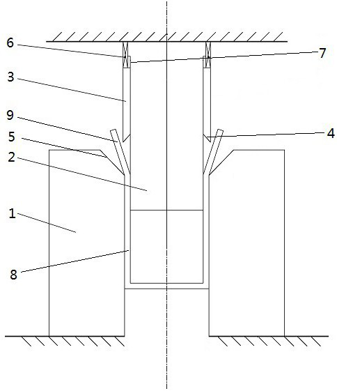
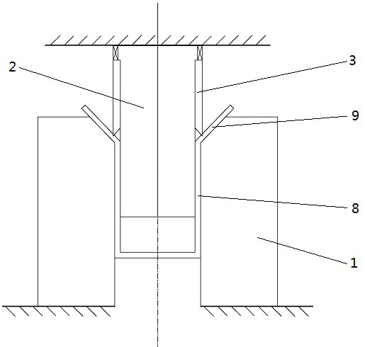
[0023] An edge trimming device for thin-walled drawing cylindrical parts, comprising an upper die seat and a lower die seat, a cylindrical part trimming mechanism is arranged between the upper die seat and the lower die seat, and the cylindrical part is cut The edge mechanism includes a concave die 1, a core punch 2, a punching connecting sleeve 3, and a cylindrical knife 4. The core punching mold 2 and the punching connecting sleeve 3 are arranged above the concave mold 1, and the concave mold 1, The axes of the fixed core punch 2 and the punching connecting sleeve 3 are located on the same vertical line, the lower end of the concave mold 1 is fixedly connected with the lower mold base, and the upper end of the inner hole of the concave mold 1 extends upward and outward to form a bevel cut The supporting surface 5, the upper end of t...


PUM


Abstract

The invention relates to the field of die manufacturing of cylindrical parts, in particular to an edge cutting device and an edge cutting method for a thin-wall deep-drawn cylindrical part. The edge cutting device for the thin-wall deep-drawn cylindrical part comprises an upper die holder and a lower die holder. A cylindrical part edge cutting mechanism is arranged between the upper die holder andthe lower die holder. The cylindrical part edge cutting mechanism comprises a female die, a fixed core male die, a buffer spring, a blanking connecting sleeve and a cylindrical cutter. A beveling supporting face is formed at the upper end of an inner hole of the female die, and the blanking connecting sleeve is arranged on the outer side of the fixed core male die. The upper end of the blanking connecting sleeve is connected with the upper die base through the buffer spring, the lower end of the blanking connecting sleeve is connected with the cylindrical cutter, and the distance between theblade of the cylindrical cutter and the axis of the blanking connecting sleeve is not smaller than the half of the width of the inner hole of the female die. According to the edge cutting method for the thin-wall deep-drawn cylindrical part, the cylindrical part is placed in the female die, the fixed-core male die and the blanking connecting sleeve move downwards, and the cylindrical cutter cuts off peripheral excess materials. The cost is low, the cylindrical part is free of burrs after edge cutting, the efficiency is high, and the device and the method can be combined with a preceding stamping procedure for progressive die in-series connection.

Description

technical field [0001] The invention relates to the field of mold making for cylindrical parts, in particular to an edge trimming device and method for thin-wall deep drawing cylindrical parts. Background technique [0002] The deep drawing process is a common processing method that uses a mold to press a flat blank into a variety of open hollow workpieces. It is widely used in industries such as automobiles, electronics, and electrical appliances. The amount, that is, the circumferential residual material, is cut off after the drawing is completed. The commonly used trimming process is mainly mechanical processing or rotary cutting method, but this method is used to remove thin-walled deep-drawing cylindrical parts. When trimming the margin, it is easy to cause processing deformation and high cost. In addition, the oblique slider mechanism is generally used in the stamping die to convert the vertical motion of the die into a horizontal and linear motion, thereby realizing t...

Claims


Application Information

Patent Timeline
IPC IPC(8): B21D37/08B21D37/12B21D35/00
CPCB21D35/002B21D37/08B21D37/12
Inventor 柴春平庄新村窦立法
Owner WEIHAI HUABANG FINE BLANKING
Why Eureka
Try Eureka