Airflow circulation structure and dehumidifier

A technology of airflow circulation and air cavity, which is applied in the direction of mechanical equipment, control input related to air characteristics, household heating, etc., and can solve problems such as easy frosting and heat dissipation

Active Publication Date: 2020-10-30
GREE ELECTRIC APPLIANCES INC
View PDF5 Cites 0 Cited by
  • Summary
  • Abstract
  • Description
  • Claims
  • Application Information

AI Technical Summary

Problems solved by technology

[0003] The present invention proposes an air circulation structure and a dehumidifier, which

Method used


Image

  • Airflow circulation structure and dehumidifier
  • Airflow circulation structure and dehumidifier
  • Airflow circulation structure and dehumidifier

Examples


Embodiment Construction

[0019] In order to make the technical problems, technical solutions and beneficial effects to be solved by the present invention clearer, the present invention will be further described in detail below in conjunction with the accompanying drawings and embodiments. It should be understood that the specific embodiments described here are only used to explain the present invention, not to limit the present invention.

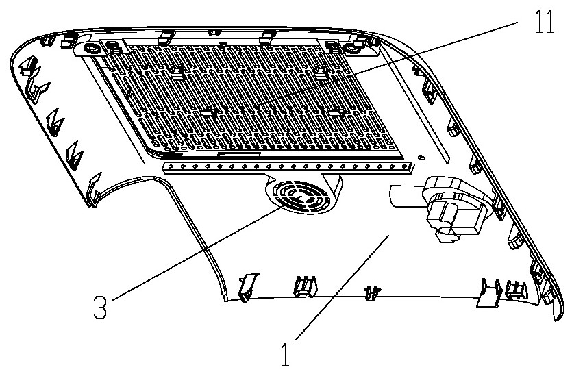
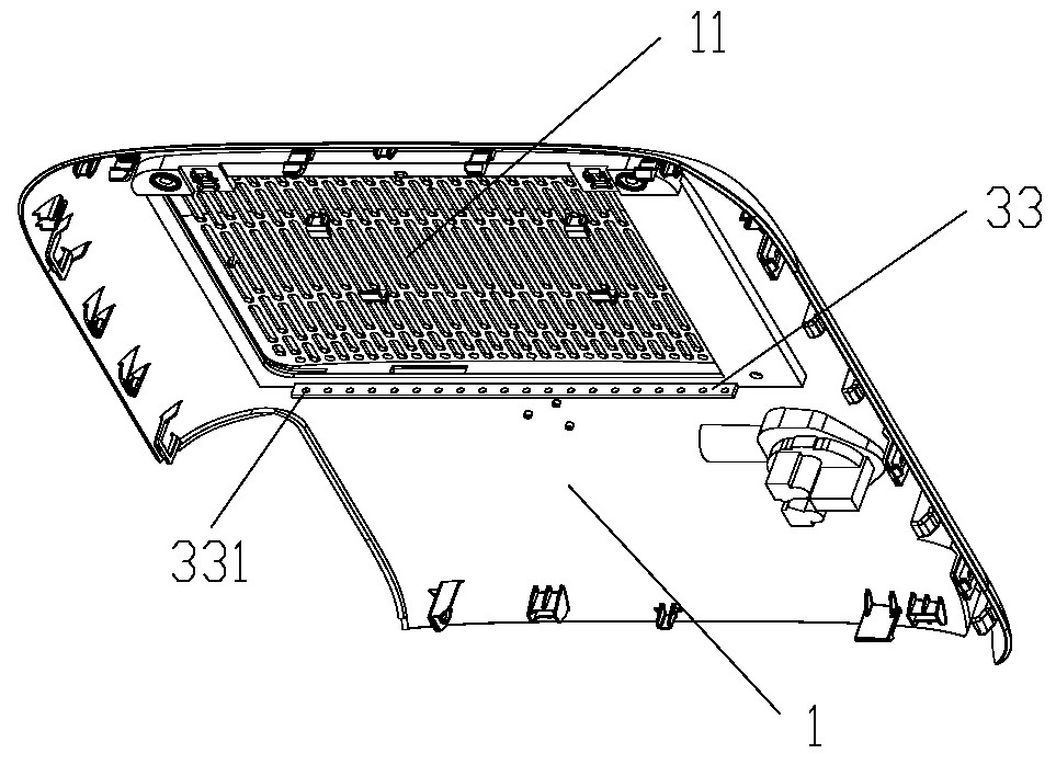
[0020] The present invention proposes an air circulation structure, such as figure 1 , 2 As shown, the airflow circulation structure is used in air treatment equipment. In this application, a dehumidifier is taken as an example for specific description. The airflow circulation structure includes: a housing 1 with an air inlet 11; A heating device that generates heat during work. The heating device is specifically a compressor 2 in the dehumidifier; the air supply unit 3 is arranged inside the housing 1, and the air supply unit 3 is used to reduce the surrounding t...


PUM


Abstract

The invention discloses an airflow circulation structure and a dehumidifier. The airflow circulation structure comprises a shell, a heating device and an air supply component, wherein the heating device and the air supply component are arranged in the shell. The air supply component comprises a cover and a driving device, wherein the cover and the driving device are spliced with the shell to forman air cavity; the shell comprises an air outlet plate; the air outlet plate comprises an air outlet; the cover comprises an air suction hole; the air cavity comprises an air suction cavity and an airoutlet cavity; the inner space of the air cavity is diffused from the air suction cavity to the air outlet cavity; and the driving device comprises a motor and fan blades. The airflow circulation structure further comprises a controller and a temperature sensor. Compared with the prior art, the airflow circulation structure can improve the air inlet temperature of the dehumidifier and alleviate the frosting problem of the dehumidifier; and meanwhile, the temperature of a heating structure can be reduced, and the heat dissipation performance of the dehumidifier can be improved.

Description

technical field [0001] The invention relates to the technical field of air treatment equipment, in particular to an air circulation structure and a dehumidifier. Background technique [0002] At present, dehumidifiers are used more and more widely in daily life. Due to their particularity, dehumidifiers can be used in low temperature and high humidity, high temperature and high humidity environments. However, with the expansion of the scope of application of dehumidifiers, they are also used in different environments. There are many defects, for example: when the dehumidifier is running in a low-temperature environment, due to the low inlet air temperature, the temperature of the evaporator may be lower than 0°C during heat exchange and dehumidification, which will cause frosting on the evaporator and affect the dehumidification effect; at the same time, When the dehumidifier operates in a high-temperature and high-humidity environment, due to the large operating load of the...

Claims


Application Information

Patent Timeline
IPC IPC(8): F24F13/00F24F13/20F24F11/89F24F11/41F24F3/14F24F110/10F24F140/20
CPCF24F3/1405F24F13/00F24F13/20F24F2013/202F24F2013/205F24F2013/207F24F11/41F24F11/89F24F2110/10F24F2140/20
Inventor 侯帅飞黄家璟姚新祥姚刚何炜向国喜
Owner GREE ELECTRIC APPLIANCES INC
Why Eureka
Try Eureka