Safe and environment-friendly low-voltage power distribution cabinet

A safety and environmental protection, power distribution cabinet technology, applied in the substation/distribution device shell, fire rescue and other directions, can solve the problem of no automatic fire extinguishing device, and the fire extinguishing method is not environmentally friendly and unsafe.

Inactive Publication Date: 2020-11-17
NINGBO LIGONG SMART GRID TECH
View PDF6 Cites 4 Cited by
  • Summary
  • Abstract
  • Description
  • Claims
  • Application Information

AI Technical Summary

Problems solved by technology

[0004] The purpose of the present invention is to solve the disadvantages in the prior art that there is no automatic fire extinguishing device, which is very unsafe, and at

Method used


Image

  • Safe and environment-friendly low-voltage power distribution cabinet
  • Safe and environment-friendly low-voltage power distribution cabinet
  • Safe and environment-friendly low-voltage power distribution cabinet

Examples


Embodiment 1

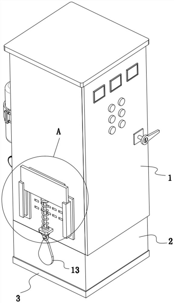
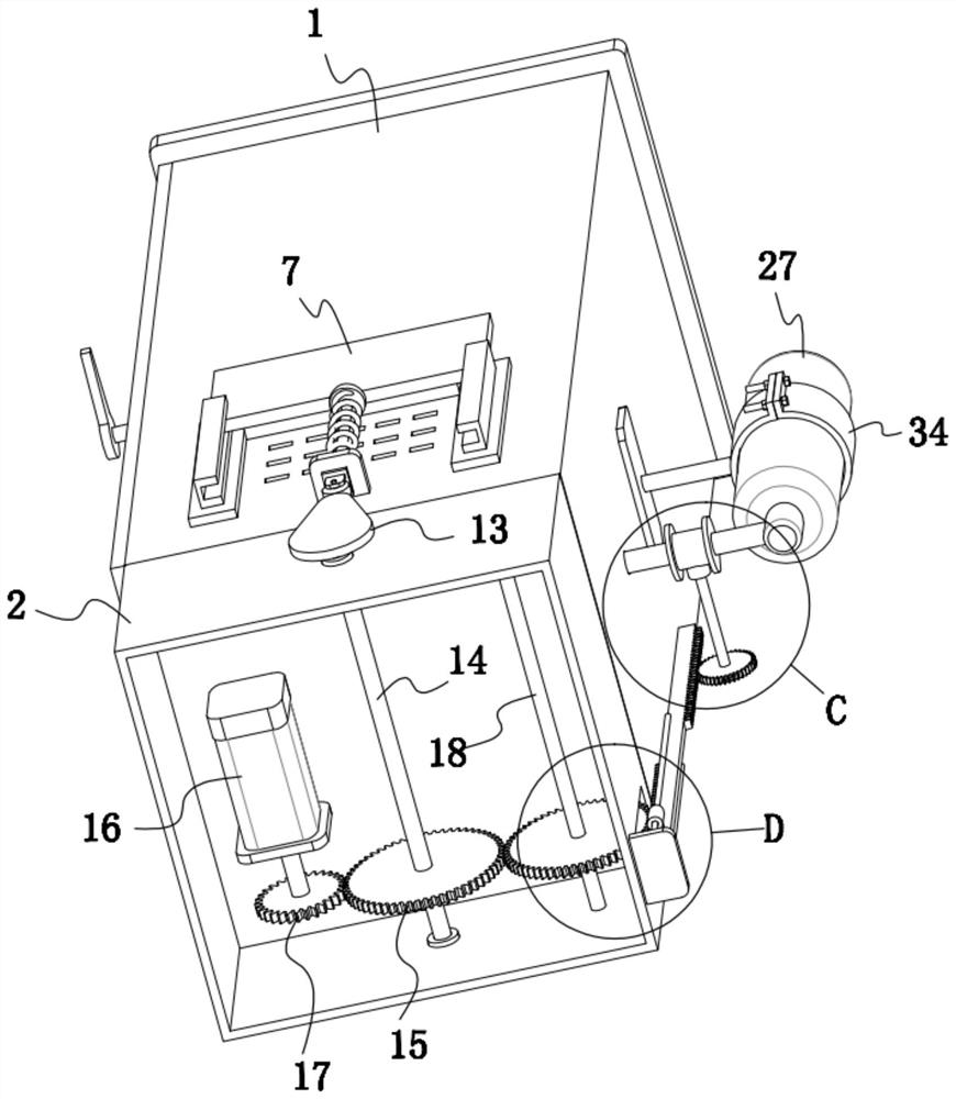
[0030] refer to Figure 1-11, a safe and environment-friendly low-voltage power distribution cabinet, including a cabinet body 1, a rectangular tube 2 is fixedly installed at the bottom of the cabinet body 1, a bottom plate 3 is fixedly installed at the bottom of the rectangular tube 2, and two corresponding sides of the cabinet body 1 are respectively There are several evenly distributed ventilation openings 4, and a connection plate 5 is fixedly installed on both sides of each group of adjacent ventilation openings 4 by screws, and a vertically arranged U-shaped plate 6 is fixedly installed on the connection plate 5. , and two U-shaped plates 6 are arranged corresponding to each other, and a sliding plate 7 matching it is inserted between the two U-shaped plates 6, and a flexible sealing plate 8 is fixedly installed on the inner surface of the sliding plate 7, and the flexible sealing plate 8 The inner surface is in contact with the surface of the cabinet body 1, and the fle...

Embodiment 2

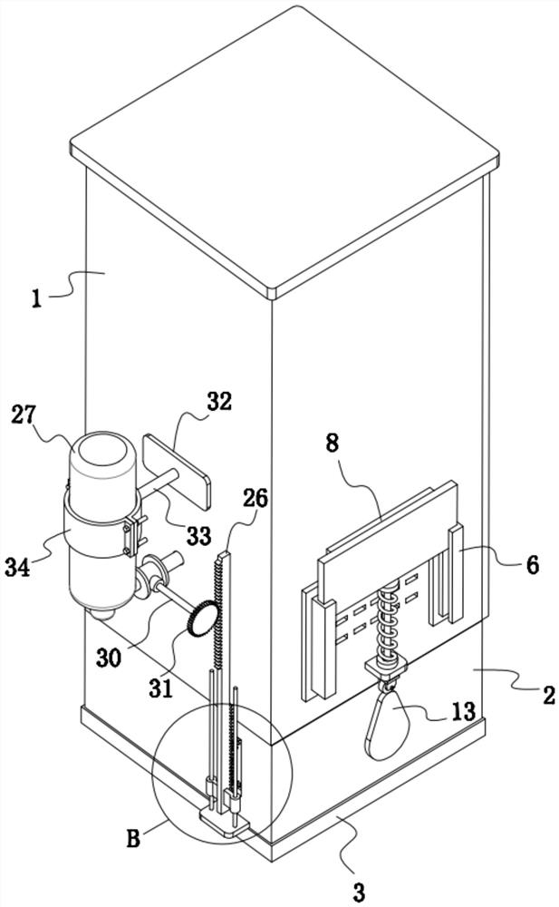
[0037] After the flexible sealing plate 8 in Example 1 blocks the vent 4, because there is still a certain amount of oxygen in the cabinet 1, before the oxygen is consumed, the combustion in the cabinet 1 still continues, which will cause equipment damage ; refer to Figure 1-11 , as another preferred embodiment of the present invention, the difference from Embodiment 1 is that an inverted inert gas storage bottle 27 is fixedly installed on the back side outer wall of the cabinet body 1 through a clamping mechanism, and an inverted inert gas storage bottle 27 is fixedly installed on the back side outer wall of the cabinet body 1 There is a gas outlet pipe 28 corresponding to the inert gas storage bottle 27, and the gas outlet pipe 28 is arranged perpendicular to the outer wall surface of the back side of the cabinet body 1. The gas outlet pipe 28 and the inert gas storage bottle 27 are fixedly connected by a valve 29, and the valve on the valve 29 The rod 30 is connected to th...


PUM


Abstract

The invention relates to the technical field of power distribution cabinets, in particular to a safe and environment-friendly low-voltage power distribution cabinet which is characterized in that a bottom plate is fixedly mounted at the bottom end of a rectangular cylinder, a plurality of uniformly distributed ventilation openings are formed in two corresponding side surfaces of a cabinet body respectively, and connecting plates are fixedly mounted on two sides of each group of adjacent ventilation openings through screws respectively; each connecting plate is fixedly provided with a vertically-arranged U-shaped plate, a sliding plate matched with the two U-shaped plates is inserted between the two U-shaped plates, the inner side face of each sliding plate is fixedly provided with a flexible sealing plate, the inner side faces of the flexible sealing plates make contact with the surface of the cabinet body, and the flexible sealing plates cover all the ventilation openings. The bottomend of each sliding plate is fixedly connected with a lifting movement mechanism, and the two lifting movement mechanisms are in transmission connection to the same driving module. By arranging the flexible sealing plate capable of ascending and descending and the inert gas storage bottle capable of injecting inert gas into the cabinet body, fire extinguishing operation can be automatically conducted, and meanwhile, the fire extinguishing mode is quite environmentally friendly.

Description

technical field [0001] The invention relates to the technical field of power distribution cabinets, in particular to a safe and environment-friendly low-voltage power distribution cabinet. Background technique [0002] Power distribution cabinets are divided into power distribution cabinets, lighting distribution cabinets, and metering cabinets, and are the final equipment of the power distribution system. The power distribution cabinet is a general term for the motor control center. The power distribution cabinet is used in the occasions where the load is relatively scattered and there are few circuits; the motor control center is used in the occasions where the load is concentrated and there are many circuits. They distribute the electric energy of a certain circuit of the upper-level power distribution equipment to the nearest load. This level of equipment shall provide protection, monitoring and control of the load. The rated current of the low-voltage power distribut...

Claims


Application Information

Patent Timeline
IPC IPC(8): H02B1/30H02B1/28A62C3/16A62C35/02A62C37/42
CPCH02B1/30H02B1/28A62C3/16A62C35/023A62C37/42
Inventor 陈吉宇
Owner NINGBO LIGONG SMART GRID TECH
Why Eureka
Try Eureka