Cutting device for aluminum alloy window frame machining

A cutting device, aluminum alloy technology, applied in the direction of shearing device, metal processing equipment, metal processing machinery parts, etc., to achieve the effect of ensuring the collection effect

Active Publication Date: 2020-12-18
重庆市东余塑钢有限公司
View PDF14 Cites 2 Cited by
  • Summary
  • Abstract
  • Description
  • Claims
  • Application Information

AI Technical Summary

Problems solved by technology

[0004] Aiming at the deficiencies of the prior art, the present invention provides a cutting device for processing aluminum alloy window fr

Method used


Image

  • Cutting device for aluminum alloy window frame machining
  • Cutting device for aluminum alloy window frame machining
  • Cutting device for aluminum alloy window frame machining

Examples


Example Embodiment

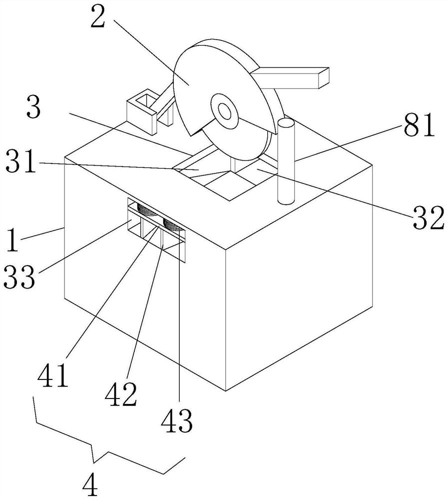
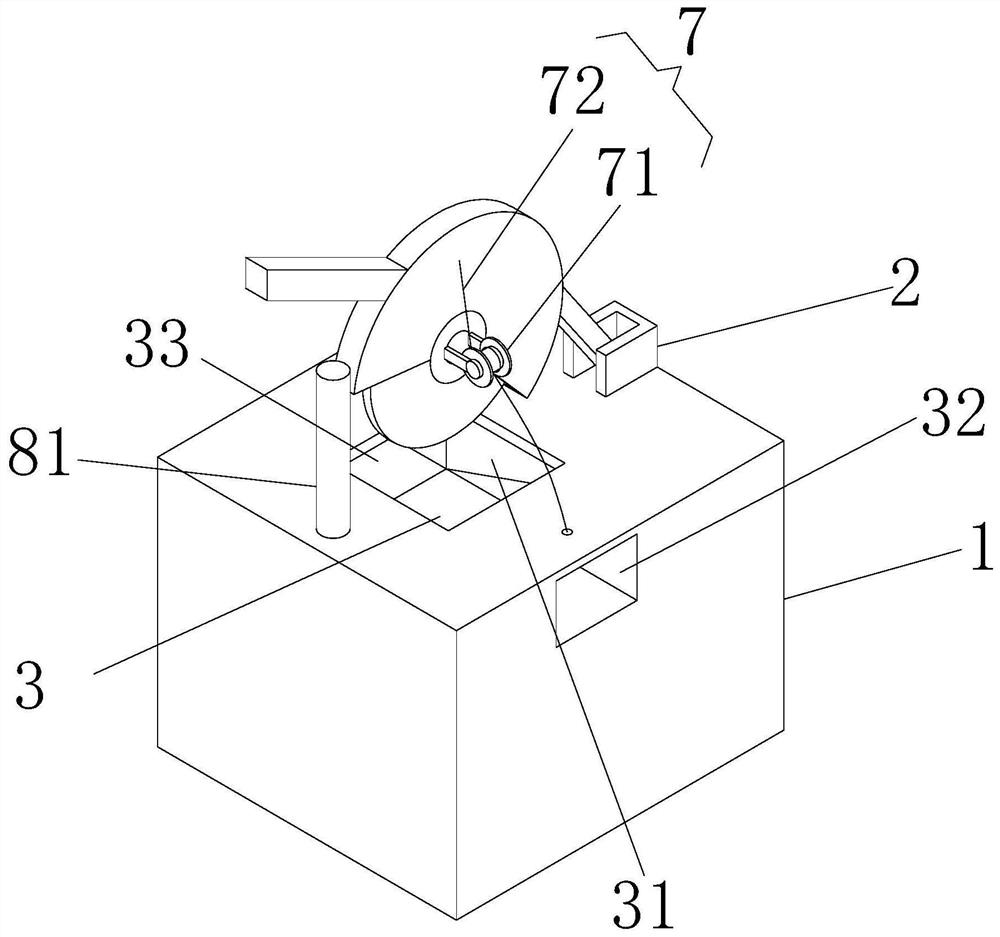
[0028]Example 1: Please refer toFigure 1-4 , A cutting device for processing aluminum alloy window frames, comprising a cutting table 1 and a cutting machine 2. The cutting machine 2 is arranged above the cutting table 1, and the cutting machine 2 and the cutting table 1 are movably connected, and the cutting table 1 is located on the cutting table. The position below the cutting knife of the machine 2 is provided with a cutting slot 3. The cutting slot 3 is provided with an air outlet slot 34, a dust collection slot 31, an inlet slot 33 and a positioning slot 32, respectively, through the cutting table. 1. The left and right sides are opened, the inlet groove 33 is provided with a clamping mechanism 4, the positioning groove 32 is provided with a positioning linkage mechanism 5, and the air outlet groove 34 is provided with an air outlet mechanism 6, and the dust collecting groove 31 gradually changes from front to back The narrowing groove, and the end of the dust collecting groo...

Example Embodiment

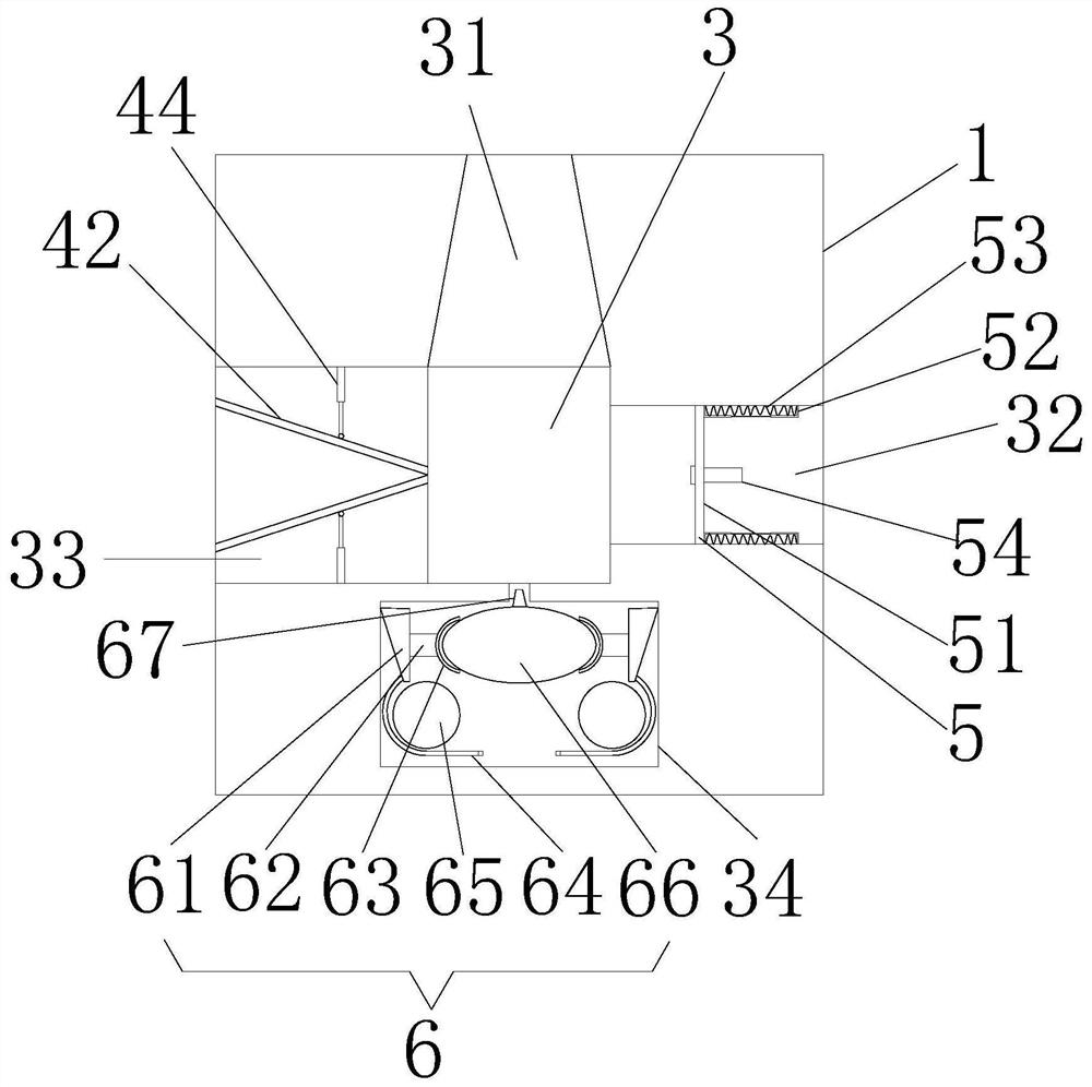
[0029]Example 2: On the basis of Example 1, please refer tofigure 1 withimage 3 The clamping mechanism 4 includes a height clamping plate 41. The height clamping plate 41 is a plate body whose width is adapted to the width of the inlet slot 33. A height-limiting spring 43 is arranged above the height-limiting plate 41. The height clamp plate 41 is laid on the upper surface, and one end of the height limit spring 43 is fixedly connected with the height clamp plate 41, the other end of the height limit spring 43 is fixedly connected with the upper wall surface of the inlet groove 33, and the height clamp plate 41 is arranged below There are two inclined clamping plates 42, which are arranged front and rear. The length of the inclined clamping plate 42 matches the length of the inlet slot 33, and the two inclined clamping plates 42 open on one side away from the cutting slot 3 Larger, that is, the side of the two inclined clamping plates 42 close to the cutting slot 3 is in contact, th...

Example Embodiment

[0030]Example 3: On the basis of Example 2, please refer toimage 3 , The width of the positioning groove 32 is adapted to the distance between the two telescopic connecting rods 44, the positioning linkage mechanism 5 includes a positioning plate 51, and the length and height of the positioning plate 51 are adapted to the width and height of the positioning groove 32, The right side of the positioning plate 51 is provided with a movable telescopic frame 52, the number of movable telescopic frames 52 is two, and the two movable telescopic frames 52 are respectively arranged on the opposite wall surfaces of the front and rear sides of the positioning groove 32, and the two movable telescopic frames 52 are provided Both ends of the spring 53 are fixedly connected to the left and right ends of the movable telescopic frame 52. The end of the movable telescopic frame 52 close to the positioning plate 51 is fixedly connected to the position corresponding to the positioning plate 51. One en...


PUM


Abstract

The invention relates to the technical field of aluminum alloy door and window machining, and discloses a cutting device for aluminum alloy window frame machining. The cutting device comprises a cutting table and a cutting machine, the cutting machine is arranged above the cutting table and movably connected with the cutting table, and a cutting groove is formed in the position, below a cutting knife of the cutting machine, of the cutting table; and an air outlet groove, a dust collecting groove, an inlet groove and a positioning groove are formed in the front, back, left and right sides in the cutting groove correspondingly. According to the cutting device for aluminum alloy window frame machining, cutting is conducted through the arrangement of the inlet groove, the positioning groove and the dust collecting groove, when a user conducts cutting, insertion from the position between two inclined clamping plates of the inlet groove can be achieved, an inserting end extends into the positioning groove for cutting, and the position of the dust collecting groove is the same as the cutting direction, so that chippings can be collected when an aluminum alloy window frame is cut by the cutting machine; and meanwhile, the chippings can more stably fall to the bottom of the dust collecting groove after being cut and falling due to the shape of the dust collecting groove, and therefore the collecting effect of the chippings is ensured.

Description

Technical field[0001]The invention relates to the technical field of aluminum alloy door and window processing, in particular to a cutting device for aluminum alloy window frame processing.Background technique[0002]Aluminum alloy windows are windows with frame and fan structure made of aluminum alloy building profiles. They are divided into ordinary aluminum alloy doors and windows and broken bridge aluminum alloy doors and windows. Aluminum alloy windows are beautiful, sealed and strong, and are widely used in the field of construction engineering. In home decoration, aluminum alloy doors and windows are commonly used to encapsulate balconies. Modern aluminum alloy doors and windows need to be cut when processing, but existing cutting devices are cutting When cutting, the debris generated during cutting will be collected and processed to prevent the debris from flying, but the common collection method is generally through gravity plus the rotation force generated during cutting to ...

Claims


Application Information

Patent Timeline
IPC IPC(8): B23D19/00B23D33/00B23D33/02B23Q11/00
CPCB23D19/00B23D33/00B23D33/02B23Q11/00B23Q11/005
Inventor 不公告发明人
Owner 重庆市东余塑钢有限公司
Why Eureka
Try Eureka