Refrigerating machine liquid removal system and method

An ice machine and compressor technology, applied in refrigerators, refrigeration and liquefaction, refrigeration components, etc., can solve problems such as accidental shutdown, containing liquid refrigerant, and user production impact, to improve liquid removal efficiency, improve stability, Realize the effect of automatic control

Pending Publication Date: 2020-12-18
CHONGQING GENERAL IND (GRP) LTD
View PDF0 Cites 0 Cited by
  • Summary
  • Abstract
  • Description
  • Claims
  • Application Information

AI Technical Summary

Problems solved by technology

[0003] However, the prior art has the following disadvantages: 1. The rise of the liquid level of the separator can only indicate that there is liquid refrigerant mixed in the refrigerant medium, but it cannot explain whether the separated refrigerant still contains liquid refrigerant, which may cause false shutdown. Great impact on user production
2. Since the liquid displacement pump needs to exhaust the gas in the pipeline before and after the pump before starting, and fill the pipeline of the pump body with liquid and cool it to the same temperature as the refrigerant liquid (minimum -40°C), the pump is easy to make the refrigerant gas when starting. , causing the pump to over-current trip and cannot be used
Frequent starting of the pump is likely to cause pump damage

Method used


Image

  • Refrigerating machine liquid removal system and method
  • Refrigerating machine liquid removal system and method
  • Refrigerating machine liquid removal system and method

Examples


Embodiment Construction

[0016] In order to make the purpose, technical solution and advantages of the present invention clearer, the present invention will be further described in detail below through specific implementation methods in conjunction with the accompanying drawings. It should be understood that the specific embodiments described here are only used to explain the present invention, not to limit the present invention.

[0017] The ice machine dehydration system provided in this application can be applied to large centrifugal refrigeration units for dehydration of odd refrigerants.

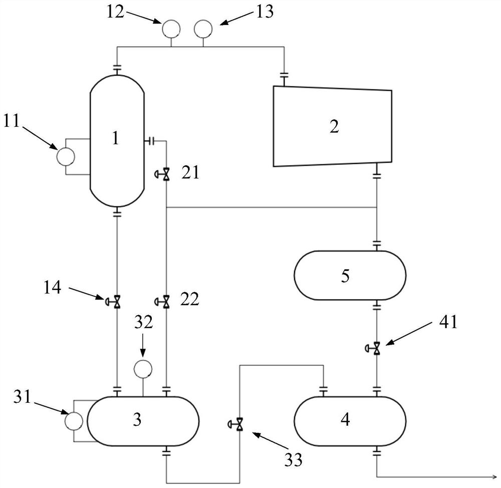
[0018] In one embodiment, such as figure 1 As shown, an ice machine dehydration system is provided, including a separator 1, a compressor 2, an intermediate tank 3, a power saver 4 and a condenser 5, wherein the upper end outlet of the separator 1 and the inlet of the compressor 2 The room is connected by a pipeline, and a first pressure transmitter 12 and a temperature transmitter 13 are arranged between the ...


PUM


Abstract

The invention provides a refrigerating machine liquid removal system and method. The method comprises the steps that through a first pressure transmitter, a temperature transmitter and a first liquidlevel transmitter which are arranged on a separator, real-time pressure, real-time temperature and liquid level height are obtained, the condensation margin of gas in the separator is calculated according to the real-time pressure and the real-time temperature, the real-time liquid level rising rate is calculated according to the liquid level height, and according to the condensation margin and the liquid level rising rate, the valve opening degree of a hot gas bypass valve is adjusted to allow hot gas to enter to vaporize liquid to complete liquid removal; and meanwhile, the liquid in the separator can flow to a middle tank through gravity, then the liquid in the middle tank is discharged into a power saver through pressure, and then the liquid is discharged to a user for use from the power saver, so that liquid removal is completed. According to the scheme, the most unit false-alarm-caused shutdown problems are solved, the probability of unit shutdown caused by false alarm is reducedby 90%, and the stability of the units is improved; and a new liquid removal mode is designed, so that the automatic control of the whole process is realized, and the liquid removal efficiency is improved.

Description

technical field [0001] The invention relates to the technical field of centrifugal refrigerators, in particular to an ice machine liquid removal system and a liquid removal method thereof. Background technique [0002] At present, the refrigeration medium of large centrifugal refrigeration units used in chemical systems generally uses ammonia or propylene. When exchanging heat on the evaporator side, the liquid refrigerant absorbs heat and becomes a gaseous refrigerant. However, due to the influence of factors such as heat exchange temperature difference and load change, a small amount of liquid refrigerant may be mixed in the gaseous refrigerant. Since the rotational speed of the centrifugal compressor impeller can reach more than 300m / s, even tiny liquid droplets will continue to impact and cause damage to the impeller. The current solution is to enter the separator before the refrigerant enters the compressor, and judge whether the unit has liquid according to the liquid...

Claims


Application Information

Patent Timeline
Patent Type & Authority Applications(China)
IPC IPC(8): F25B43/02
CPCF25B43/02
Inventor 黄袁川陈浩孙磊
Owner CHONGQING GENERAL IND (GRP) LTD
Why Eureka
Try Eureka