A threading device for an extruder

A technology of threading device and extruder, applied in the direction of conductor/cable insulation, coating, etc., can solve the problems of high labor intensity and cumbersome wiring operation, and achieve the effect of reducing labor intensity and making it easier to go online.

Active Publication Date: 2022-04-22
山东亿博光电科技有限公司
View PDF11 Cites 0 Cited by
  • Summary
  • Abstract
  • Description
  • Claims
  • Application Information

AI Technical Summary

Problems solved by technology

The wiring operation is cumbersome and labor-intensive

Method used


Image

  • A threading device for an extruder
  • A threading device for an extruder
  • A threading device for an extruder

Examples


Embodiment Construction

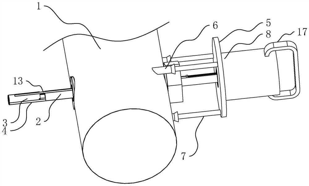
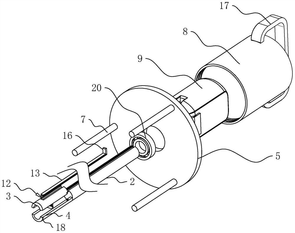
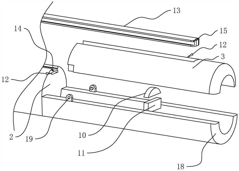
[0031] The following is attached Figure 1-2 The application is described in further detail.

[0032] The embodiment of the present application discloses a threading device of an extruder. refer to figure 1 , including a wire insertion tube 2 for passing through the die head 1, a fixing mechanism fixed at one end of the wire insertion tube 2 for fixing the wire insertion tube 2 on the die head 1, and a mechanism for driving the wire insertion tube 2 to rotate The rotating mechanism and the clamping mechanism arranged at the end of the wire insertion tube 2 away from the fixing mechanism are used for fixing a plurality of wires. When working, the staff inserts the wire insertion tube 2 from the discharge end of the die head 1 to the feed end of the die head 1, and fixes the wire insertion tube 2 on the die head 1 through a fixing mechanism, and then the staff inserts a plurality of wires The silk thread is fixedly arranged on the thread insertion tube 2, and at the same tim...


PUM


Abstract

This application relates to a threading device for an extruder, including a wire insertion tube, a fixing mechanism for fixing the wire insertion tube on the die head, a rotating mechanism for driving the wire insertion tube to rotate, and a The clamping mechanism at the mechanism end is used to fix multiple wires. The clamping mechanism includes a clamping assembly. The clamping assembly includes a hinged clamping half sleeve, a fixed clamping half sleeve, and a hinged clamping half sleeve is hinged to the insertion tube. Setting, the fixed clamping half sleeve is fixedly connected with the insertion tube, the hinged clamping half sleeve is closed with the fixed clamping half sleeve to form a tube sleeve with a circular cross section, and the clamping mechanism also includes a hinged clamping The fastening assembly used to clamp multiple wires on the half sleeve. The fixing mechanism includes a fixed plate and a pin assembly that fixes the fixed plate on the die head. One end of the wire insertion tube passes through the fixed plate, and passes through the bearing seat and the fixed plate. Turn to connect. The setting of the threading device can facilitate the staff to go online to the die head, reducing the labor intensity of the staff.

Description

technical field [0001] The present application relates to the field of extruders, in particular to a threading device for an extruder. Background technique [0002] The extruder is an important plastic machine, and the production and manufacture of most plastic products can be realized by extrusion molding. Cables, optical cables, and power cords often need to be wrapped with an insulating outer sleeve on one side by an extruder during the production process. [0003] refer to Figure 4 , the extruder includes a die head 1, the film head includes a die head body 22, the die head body 22 is provided with a feed port and a discharge port, and the feed port and the discharge port are respectively arranged on both sides of the die head body 22, And the central axes of the inlet and outlet are on the same straight line. The die head 1 also includes a discharge end 21 arranged at one end of the discharge port, and the discharge end 21 is fixedly connected with the die body 22 th...

Claims


Application Information

Patent Timeline
Patent Type & Authority Patents(China)
IPC IPC(8): B29C48/06B29C48/154B29C48/25H01B13/14
CPCB29C48/06B29C48/154B29C48/25H01B13/14
Inventor 雷明凯汪年生杨龙山张艳胡方翠
Owner 山东亿博光电科技有限公司
Why Eureka
Try Eureka