New energy automobile charging pile mounting structure

A new energy vehicle and installation structure technology, applied in the direction of electric vehicle charging technology, charging stations, electric vehicles, etc., can solve the problems of long installation and construction period, unfavorable fast disassembly and assembly of charging piles, damage to charging piles, etc. Water accumulation, improved practicability, and easy installation

Inactive Publication Date: 2021-02-05
郭连坤
View PDF0 Cites 4 Cited by
  • Summary
  • Abstract
  • Description
  • Claims
  • Application Information

AI Technical Summary

Problems solved by technology

[0004] The purpose of the present invention is to provide a new energy vehicle charging pile installation structure, which has the advantages of easy installation and anti-water accumulation, and solves the problem that when the existing new energy vehicle charging piles are installed, it is often necessary to pour concrete piers on the ground in advance. The cement fixes the charging pile to the ground, which leads to a long installation and construction period, which is not conducive to the quick disassembly and assembly of the charging pile, and when there is water on the ground, because the height of the charging pile is fixed, the ground water is easy to cause the charging pile to be damaged. The problem of water damage

Method used


Image

  • New energy automobile charging pile mounting structure
  • New energy automobile charging pile mounting structure
  • New energy automobile charging pile mounting structure

Examples


Embodiment Construction

[0025] The technical solutions in the embodiments of the present invention will be clearly and completely described below in conjunction with the accompanying drawings in the embodiments of the present invention. Obviously, the described embodiments are only some of the embodiments of the present invention, not all of them. Based on The embodiments of the present invention and all other embodiments obtained by persons of ordinary skill in the art without making creative efforts belong to the protection scope of the present invention.

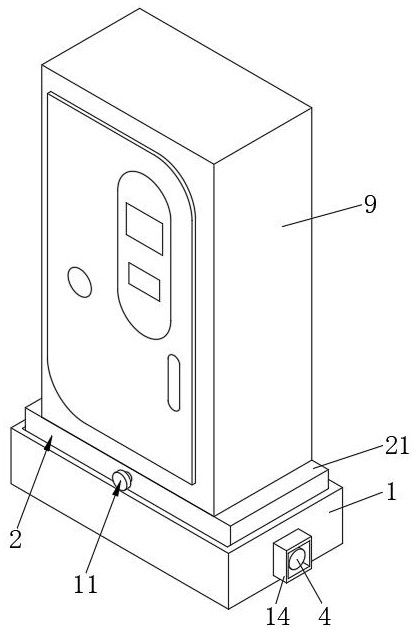
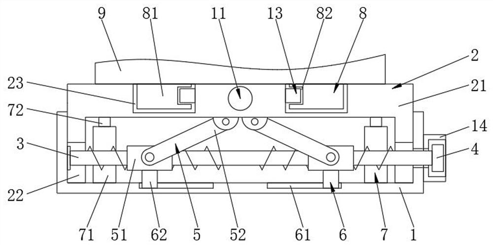
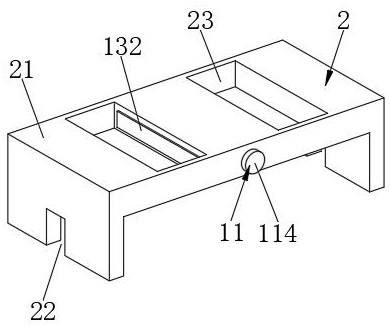
[0026] see Figure 1-4, the present invention provides a technical solution: a new energy vehicle charging pile installation structure, including a mounting base 1 and a charging pile body 9, the inner cavity of the mounting base 1 is provided with a placement mechanism 2, and the left side of the inner cavity of the mounting base 1 passes through The bearing is movably connected with a two-way threaded rod 3, and the surface of the two-way thre...


PUM


Abstract

The invention discloses a new energy automobile charging pile mounting structure, and the structure comprises a mounting base and a charging pile body; a placement mechanism is arranged in an inner cavity of the mounting base, a bidirectional threaded rod is movably connected to the left side of the inner cavity of the mounting base through a bearing, and opposite threads are arranged on the surface of the bidirectional threaded rod. The two mounting blocks are placed in the inner cavities of the two mounting grooves correspondingly, the second knob is rotated, the second knob finally drives the second wedge block to enter the inner cavity of the strip-shaped groove to lock the two mounting blocks, and the first knob and the first knob are rotated to finally drive the mounting frame and the charging pile body to ascend, so that the purposes of convenient mounting and water accumulation prevention are achieved; the new energy automobile charging pile installation structure has the advantages of being convenient to install and capable of preventing water accumulation, cement does not need to be adopted for pouring, the function of rapid disassembly and assembly is achieved, the lifting height of the charging pile can be conveniently controlled according to the installation position, and the charging pile is not prone to being soaked by accumulated water.

Description

technical field [0001] The invention relates to the technical field of charging piles, in particular to a new energy vehicle charging pile installation structure. Background technique [0002] The function of the charging pile is similar to the fuel dispenser in the gas station. It can be fixed on the ground or wall, and installed in the parking lot or charging station of public buildings and residential areas. It can charge various types of electric vehicles according to different voltage levels. The charging pile The input end of the battery is directly connected to the AC power grid, and the output end is equipped with a charging plug for charging electric vehicles. Charging piles generally provide two charging methods: conventional charging and fast charging. Swipe the card on the computer interactive operation interface to perform operations such as charging method, charging time, and cost data printing. The display screen of the charging pile can display data such as c...

Claims


Application Information

Patent Timeline
IPC IPC(8): B60L53/31B60L53/30
CPCB60L53/30B60L53/31Y02T10/70Y02T10/7072Y02T90/12
Inventor 郭连坤
Owner 郭连坤
Why Eureka
Try Eureka