Dismounting device for in-hole bearing

A technology for dismantling devices and inner bearings, which is applied in hand-held tools and manufacturing tools, etc. It can solve the problems of poor safety, high labor intensity, separation and falling off of the inner ring of the bearing, etc., to facilitate quick reset, avoid bearing damage, and ensure stability Effect

Active Publication Date: 2021-02-19
冠县恒祥轴承制造有限公司
View PDF9 Cites 0 Cited by
  • Summary
  • Abstract
  • Description
  • Claims
  • Application Information

AI Technical Summary

Problems solved by technology

[0002] With the continuous development of science and technology, bearings are an indispensable and important part of major machinery. The replacement of bearings has always been a headache for major factories, and some even replace large machinery because of a small bearing. A bad demolition will have a huge impact on the future operation of the machine
[0003] At present, the commonly used method is to disassemble it by impact. This method has low work efficiency, high labor intensity, poor safety, and is easy to damage the bearing, resulting in increased disassembly costs.
[0004] The Chinese utility model patent with the application number of 201320180666.0 discloses an inner bearing pull code, which includes a pull rod (1), and one end of the pull rod (1) is provided with a mounting head (3) for installing the pull code foot (2), and the other end A handle (4) is provided, and the pull rod (1) is provided with a slide hammer (5) that can slide axially on the pull rod (1), characterized in that the installation head (3) is detachable It is connected with the said pull code foot (2), and the described pull code foot (2) is provided with an expansion and contraction structure (6) that can radially expand or contract when the pull rod (1) rotates, and the described handle ( 4) A booster structure (7) is provided on it; when in use, the claw 62 is inserted into the bearing, and the claw 62 is fixed through the concave platform 611, and then the push rod 23 is inserted into the cylindrical body and the connecting screw 22 and the The cylindrical bodies are connected, the connecting bolt 21 is installed on the installation head 3, the claw 62 is gradually opened by the power-assisted rod 71 to rotate the pull rod 1 to fix the bearing, and the bearing is pulled out by hitting the handle 4 with the slide hammer 5; however, the bearing is disassembled It mainly depends on the friction force between the claw and the inner ring of the bearing when it is tightened. Since the claw has the function of opening and contracting, it is easy to separate and fall off the inner ring of the bearing after being impacted by the pull rod, thus affecting the disassembly operation of the bearing. , the impact force generated by the sliding hammer at the moment of impact is relatively large, which is easy to cause damage to the bearing, especially the large force on the inner ring of the bearing, causing the inner ring of the bearing to separate from the outer ring of the bearing, thus damaging the bearing

Method used


Image

  • Dismounting device for in-hole bearing
  • Dismounting device for in-hole bearing
  • Dismounting device for in-hole bearing

Examples


Embodiment Construction

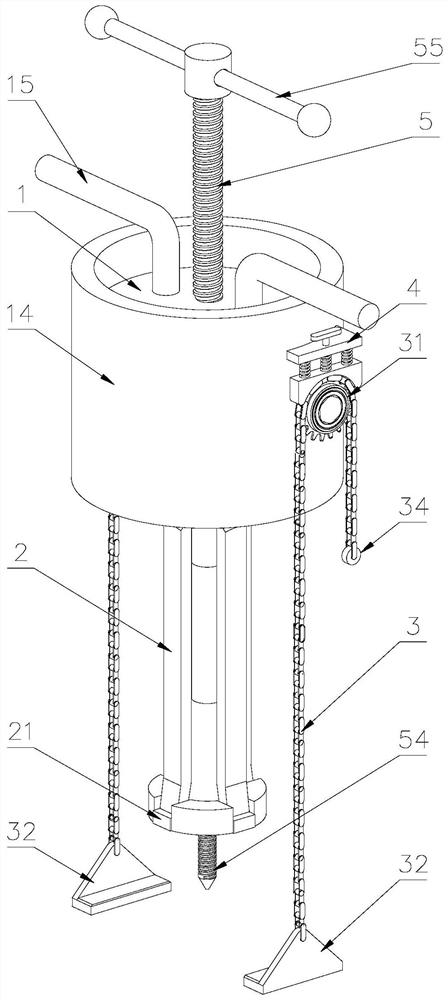
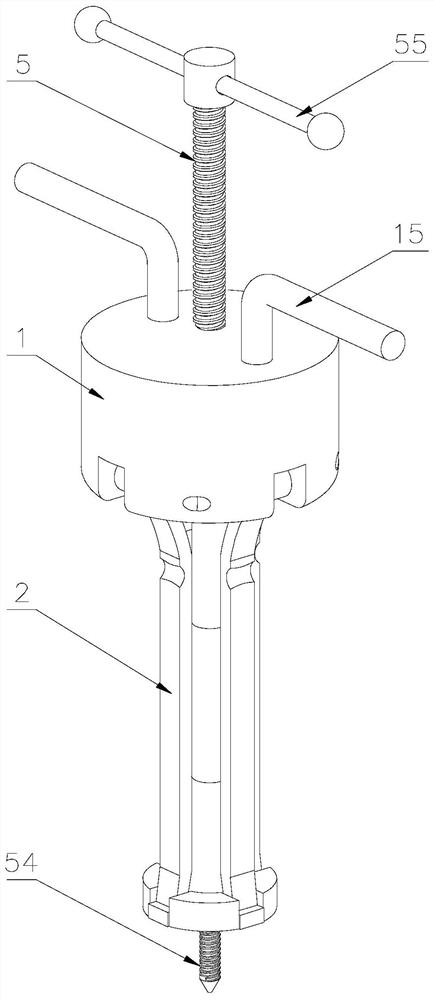
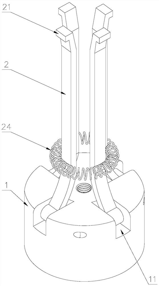
[0038] Attached below Figure 1-9 , clearly and completely describe the technical solutions in the embodiments of the present invention, obviously, the described embodiments are only some of the embodiments of the present invention, not all of them. Based on the embodiments of the present invention, all other embodiments obtained by persons of ordinary skill in the art without making creative efforts belong to the protection scope of the present invention.

[0039] In describing the present invention, it should be understood that the terms "longitudinal", "transverse", "upper", "lower", "front", "rear", "left", "right", "vertical", The orientations or positional relationships indicated by "horizontal", "top", "bottom", "inner", "outer", etc. are based on the orientations or positional relationships shown in the drawings, and are only for the convenience of describing the present invention, rather than indicating or It should not be construed as limiting the invention by imply...


PUM


Abstract

The invention discloses a dismounting device for an in-hole bearing. An inner barrel is in threaded connection with the interior of an outer barrel, a plurality of second handles are arranged on the upper portion of the inner barrel, an ejector rod is in threaded connection with the middle of the inner barrel, a conical head is arranged at the lower end of the ejector rod, and a first handle is arranged at the upper end of the ejector rod; at least two mounting grooves are formed in the lower portion of the inner barrel, clamping arms are movably connected to the mounting grooves, and a firstclamping hook is arranged at one end of each clamping arm; and at least two sets of chain wheels are arranged on the outer barrel, the chain wheels are mounted on the outer wall of the outer barrel through fixed shafts, chains are arranged on the chain wheels, and second clamping hooks are arranged at the lower ends of the chains. When the in-hole bearing is dismounted, the second clamping hooks are clamped on a bearing pedestal or other fixing structures, then the clamping arms are inserted into a bearing inner ring, the first handle is rotated, the first clamping hooks at the lower ends of the clamping arms are opened through the conical head and hook the lower end face of the bearing, then the second handles are rotated, the inner barrel ascends, the clamping arms are driven to move upwards, and therefore the in-hole bearing is dismounted, the dismounting stability of the in-hole bearing is guaranteed, and the bearing is prevented from being damaged.

Description

technical field [0001] The invention belongs to the technical field of bearing dismounting tooling, in particular to a dismounting device for bearings in bores. Background technique [0002] With the continuous development of science and technology, bearings are an indispensable and important part of major machinery. The replacement of bearings has always been a headache for major factories, and some even replace large machinery because of a small bearing. A bad demolition will have a huge impact on the future operation of the machine. [0003] At present, the commonly used method is generally to disassemble it by adopting the method of impact. This method has low work efficiency, high labor intensity, poor safety, and is easy to damage the bearing, resulting in increased disassembly cost. [0004] The Chinese utility model patent with the application number of 201320180666.0 discloses an inner bearing pull code, which includes a pull rod (1), and one end of the pull rod (1...

Claims


Application Information

Patent Timeline
Patent Type & Authority Applications(China)
IPC IPC(8): B25B27/073
CPCB25B27/062
Inventor 崔振庆
Owner 冠县恒祥轴承制造有限公司
Why Eureka
Try Eureka