Locking device for spinning spindle or twisting spindle

A spinning spindle and locking device technology, applied in the field of locking devices, can solve problems such as inability to achieve

Pending Publication Date: 2021-02-23
衡阳新新纺织机械有限公司
View PDF11 Cites 0 Cited by
  • Summary
  • Abstract
  • Description
  • Claims
  • Application Information

AI Technical Summary

Problems solved by technology

[0004] The above-mentioned patent has the following disadvantages: it aims to solve the problem of the locking stability of the spindle, because the spindle needs to cooperate with the fiber production equipment to twist the yarn synchronously during actual use, and the fiber yarn needs to have a certain tension during the spinning and winding process of the spindle , so as to meet the tension required for winding, but the above-mentioned patents are not fully disclosed and cannot meet the above-mentioned requirements, and further improvement is needed

Method used


Image

  • Locking device for spinning spindle or twisting spindle
  • Locking device for spinning spindle or twisting spindle
  • Locking device for spinning spindle or twisting spindle

Examples


Embodiment 1

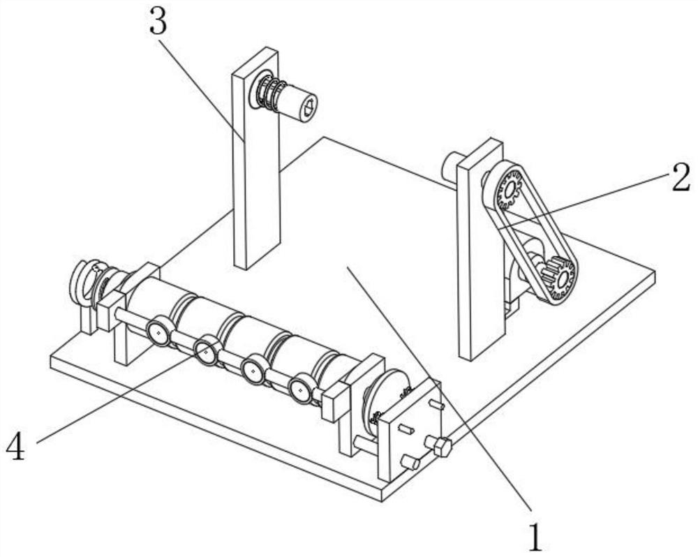
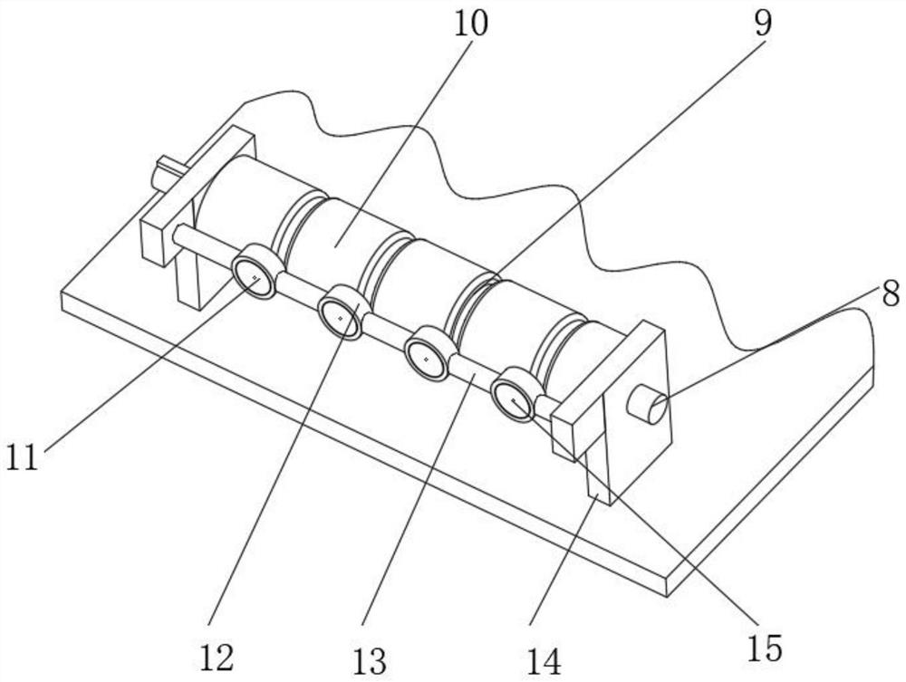
[0036] A locking device for spinning or twisting spindles, such as Figure 1-4As shown, including a base 1, the top outer wall of the base 1 is respectively provided with a clamping mechanism one 2 and a clamping mechanism two 3 that cooperate with each other, and the top outer wall of the base 1 is provided with a damping guide mechanism 4, and the damping guide The mechanism 4 includes an adjustable damping assembly 5, a guide assembly 6, and an adaptive adjustment damping assembly 7. The guide assembly 6 includes a guide roller 10 and a limit ring 12, and the outer walls on both sides of the guide roller 10 are rotated by a shaft 8 Connected with a support plate 14, the support plate 14 is fixed on the top outer wall of the base 1 by bolts, the inner wall of the guide roller 10 is provided with a guide groove 9, and the opposite side outer walls of the two support plates 14 are fixed with support rods by bolts 13. The limit ring 12 is welded on the outer wall of the support...

Embodiment 2

[0039] A locking device for spinning or twisting spindles, such as figure 1 , 6 , 7, in order to solve the spindle clamping problem; the present embodiment makes the following improvements on the basis of embodiment 1: the clamping mechanism-2 includes a deck-31 and a deck-31, and the deck-31 The outer wall of the outer wall is connected with the support plate 2 30 through the rotation of the shaft 2 32, the support plate 30 is fixed on the top outer wall of the base 1 by bolts, the motor 35 is fixed on the top outer wall of the base 1 by bolts, the output shaft of the motor 35 and the shaft 2 The outer walls of 32 are all connected with sprockets 34 by keys, and the two sprockets 34 establish transmission cooperation through chains 33. The clamping mechanism 2 3 includes support plates 3 36 and deck 2 40, and the support plates 3 36 are connected by bolts. Fixed on the top outer wall of the base 1, the inner wall of the support plate 3 36 is rotatably connected with the rota...

Embodiment 3

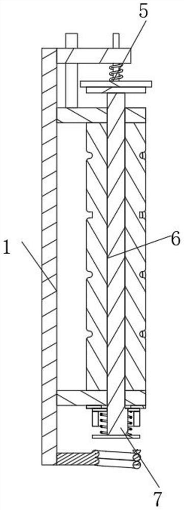
[0042] A locking device for spinning or twisting spindles, such as Figure 5 As shown, in order to solve the reliability problem; the self-adaptive adjustment damping assembly 7 includes friction disc three 23 and friction disc four 24, and the friction disc three 23 is fixed on the outer wall of one side of support plate one 14 by bolts, and the friction disc The inner wall of four 24 is movably connected with the key-shaped protrusion-22 by the shaft-8 which is arranged on the key-shaped protrusion-22, and the outer wall of one side of the shaft-8 is fixed with a baffle plate 29 by bolts, and the baffle plate 29 and the friction disc 4 24 is provided with spring two 26, and the outer wall of friction disc four 24 is fixedly equipped with magnetic ring 25, and coil 28 is fixed on the top outer wall of base 1 by coil support 27, and described coil 28 and motor 35 are connected in series in the same circuit, And the direction of the magnetic field generated by the coil 28 is op...


PUM


Abstract

The invention discloses a locking device for a spinning spindle or a twisting spindle, and relates to the technical field of spinning. The device aims to solve the problem of tension. The device specifically comprises a base; a first clamping mechanism and a second clamping mechanism which are matched with each other are arranged on the outer wall of the top of the base; a damping type guide mechanism is arranged on the outer wall of the top of the base; the damping type guide mechanism comprises an adjustable damping assembly, a guide assembly and a self-adaptive adjusting damping assembly; the guide assembly comprises a guide roller and a limiting ring; the outer walls of the two sides of the guide roller are rotationally connected with first supporting plates through first shafts; the first supporting plates are fixed to the outer wall of the top of the base through bolts; the adjustable damping assembly comprises a first friction disc and a second friction disc; the first frictiondisc is fixed to the outer wall of the first shaft through a bolt; a first sliding rod is fixed to the outer wall of one side of the first supporting plate through a bolt; and a sliding plate is slidably connected with the outer wall of the first sliding rod. The locking device for the spinning spindle or the twisting spindle can ensure the fiber tension between the guide roller and the spindles.

Description

technical field [0001] The invention relates to the technical field of textiles, in particular to a locking device for a spinning spindle or a twisting spindle. Background technique [0002] Spindle is one of the main components of twisting and winding on the spinning machine. It is generally an assembly with a slender rotary shaft supported by two points as the main body. There are spindles on the roving frame, spinning frame and twisting frame. The spindle is actually used A locking device, that is, a fixing device, is needed when it is used to drive the spindle to rotate, so as to twist the fiber into something and wind it into a certain shape. [0003] After searching, the Chinese patent publication number is CN102286814B, which discloses a locking device for spinning spindles or twisting spindles, wherein the spinning spindles or twisting spindles have an upper half of the spindle, and the upper half of the spindle has a driving spindle plate, and the upper part of the...

Claims


Application Information

Patent Timeline
IPC IPC(8): D01H7/08
CPCD01H7/08
Inventor 曾贤通彭来深焦贤伟谭新球
Owner 衡阳新新纺织机械有限公司
Why Eureka
Try Eureka