Imaging thin film and electronic equipment shell

A thin film and imaging technology, applied in optics, lenses, instruments, etc., can solve problems such as insufficient resolution, high cost, and high price

Pending Publication Date: 2021-03-16
SHINE OPTOELECTRONICS KUNSHAN CO LTD
View PDF4 Cites 0 Cited by
  • Summary
  • Abstract
  • Description
  • Claims
  • Application Information

AI Technical Summary

Problems solved by technology

However, these technical solutions will bring some technical problems. The first technical solution is achieved through color matching, so that the resolution of the product is not high enough, and dots appear; the product formed by the second technical solution is in graphic There will be instability and poor repeatability between them; the third effect of using magnetic powder to achieve gradual changes is too costly, and the price is relatively high as an industrial production

Method used


Image

  • Imaging thin film and electronic equipment shell
  • Imaging thin film and electronic equipment shell
  • Imaging thin film and electronic equipment shell

Examples


Embodiment Construction

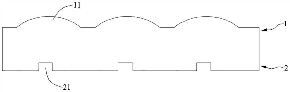
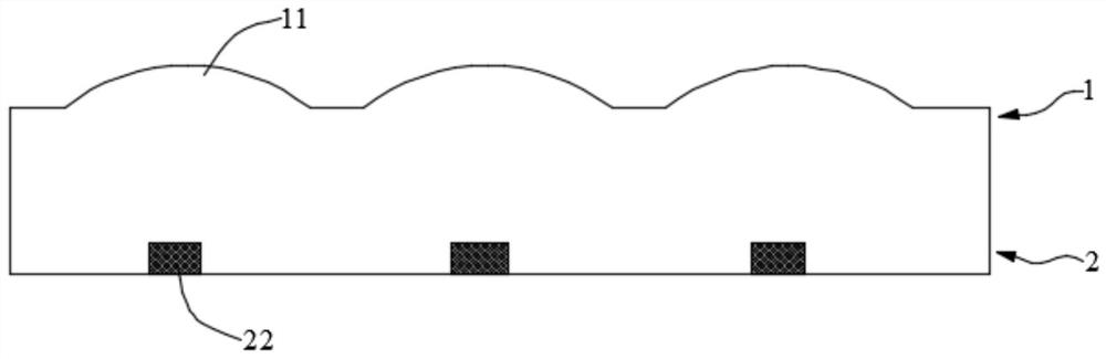
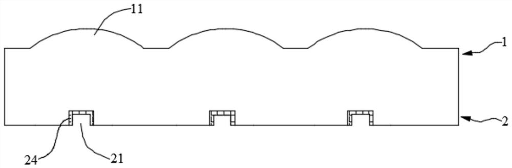
[0062] In order to make the object, technical solution and advantages of the present invention clearer, the present invention will be further described in detail below in conjunction with the accompanying drawings and embodiments. It should be understood that the specific embodiments described here are only used to explain the present invention, not to limit the present invention.

[0063] In the description of the present invention, unless otherwise clearly specified and limited, the terms "first" and "second" are only used for the purpose of description, and cannot be understood as indicating or implying relative importance; unless otherwise specified or illustrated , the term "plurality" refers to two or more; the terms "connection", "fixation" and so on should be understood in a broad sense, for example, "connection" can be a fixed connection, a detachable connection, or an integrated Connected, or electrically connected; either directly or indirectly through an intermedia...


PUM

PropertyMeasurementUnit
transmittivityaaaaaaaaaa

Abstract

The invention relates to the technical field of optical thin films, in particular to an imaging thin film and an electronic equipment shell. The imaging thin film comprises a body, the body is provided with two opposite sides, a focusing layer is formed on one side, and an image-text layer is formed on the other side, wherein the image-text layer has gradual change, the image-text layer is matchedwith the focusing layer so as to form an image through the focusing layer, and the image has a gradual change effect. The image-text layer of the imaging thin film provided by the invention has gradual change, so that the formed image has a gradual change effect, the imaging thin film has a gradual change and three-dimensional effect, and the imaging thin film has an attractive effect when beingused for an electronic equipment shell.

Description

technical field [0001] The invention relates to the technical field of optical thin films, in particular to an imaging thin film and an electronic equipment casing. Background technique [0002] Many existing technical fields require the color or graphics of the product to have a gradient effect, which gives people a visual transition and can also play a safe role to some extent; for example, the casing of electrical appliances on the existing product market , the shell of the mobile phone, or the film on some electronic devices, or the film on the vehicle also needs a gradient effect. [0003] There are many options for the technical solutions used in the color gradient in the prior art, for example: using printing technology to print different inks, producing gradients by toning the colors or patterns; or obtaining the effect of color gradients by pulling , or use magnetic powder materials to achieve color gradient effects. However, these technical solutions will bring s...

Claims


Application Information

Patent Timeline
Patent Type & Authority Applications(China)
IPC IPC(8): G02B3/00G02B30/27
CPCG02B3/00
Inventor 刘立冬宋忠阳包卫英江州
Owner SHINE OPTOELECTRONICS KUNSHAN CO LTD
Why Eureka
Try Eureka