Optical splitter with adjustable splitting ratio, optical fiber distribution box and optical distribution network

A technology of optical splitter and optical splitting ratio, which is applied in optical fiber transmission, coupling of optical waveguides, optical guides, etc.

Active Publication Date: 2021-03-16
HUAWEI TECH CO LTD
View PDF8 Cites 3 Cited by
  • Summary
  • Abstract
  • Description
  • Claims
  • Application Information

AI Technical Summary

Problems solved by technology

[0005] This application provides an optical splitter with adjustable splitting ratio, an optical fiber splitting box and an optical di

Method used


Image

  • Optical splitter with adjustable splitting ratio, optical fiber distribution box and optical distribution network
  • Optical splitter with adjustable splitting ratio, optical fiber distribution box and optical distribution network
  • Optical splitter with adjustable splitting ratio, optical fiber distribution box and optical distribution network

Examples


Embodiment Construction

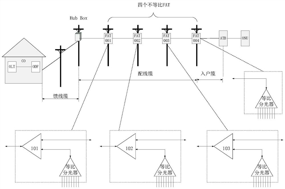
[0057] In order to make those skilled in the art better understand the technical solutions provided by the embodiments of the present application, the application scenarios of the optical splitter are firstly introduced below. figure 1 shows an ODN, such as figure 1 As shown, one side of the ODN is an OLT, and the other side is an ONU. The OLT and optical distribution frame (Optical Distribution Frame, ODF) are located in the Central Office (Central Office, CO). The direction from OLT to ONU is the downlink transmission direction; the direction from ONU to OLT is the uplink transmission direction. Take the downlink transmission direction as an example. In the downlink transmission direction, the optical signal of the OLT passes through the ODF and then passes through the feeder cable to reach the hub (Hub Box), and the signal of the Hub Box reaches all levels of FAT through the distribution cable, that is, the first level of FAT 001 , the second level FAT 002, the third leve...


PUM


Abstract

The invention discloses an optical splitter with an adjustable splitting ratio, an optical fiber distribution box and an optical distribution network. The optical splitter comprises a first structuralmember, a second structural member and an adjusting member. The first structural member comprises a lens and a slot. The second structural member includes two lenses and two slots, and the two lensesare relatively offset in the first direction. Slots are used for accommodating optical fibers. The first structural member or the second structural member is connected with the adjusting member, andwhen the adjusting member moves, relative deviation of the first structural member and the second structural member in the first direction can be changed, so that the proportion of light beams projected to the second structural member by the first structural member is changed. The splitting ratio of the two paths of light can be freely adjusted only by moving the adjusting member in the optical splitter, so that the expected splitting ratio is achieved. The light splitter can meet various different light splitting requirements, does not need to introduce various different types of light splitters to split light beams into two parts, and solves the problem of misuse caused by the fact that the types of the light splitters are numerous and are difficult to distinguish.

Description

technical field [0001] The present application relates to the technical field of optical access network, in particular to an optical splitter with adjustable splitting ratio, an optical fiber splitting box and an optical distribution network. Background technique [0002] An optical splitter, also known as an optical splitter, is a passive fiber branching device commonly used in a passive optical network (Passive Optical Network, PON). As a passive device connecting an Optical Line Terminal (OLT) and an Optical Network Unit (ONU), an optical splitter can distribute downlink data to the ONU, and can also centralize uplink data to the OLT. At present, optical splitters can be used in various node products in Optical Distribution Network (ODN), such as Optical Distribution Frame (ODF), Fiber Distribution Terminal (FDT), Fiber Access Terminal (FAT), Closure, etc. [0003] In some application scenarios, ODN needs to use a unequal network including multi-level FAT to realize opt...

Claims


Application Information

Patent Timeline
IPC IPC(8): G02B6/42G02B6/44H04B10/25
CPCG02B6/4204G02B6/4452G02B6/4446G02B6/4471H04B10/25
Inventor 魏素朱桦李书
Owner HUAWEI TECH CO LTD
Why Eureka
Try Eureka